Subaru Legacy IV (2008 year). Manual - part 31


  Index      Subaru     Subaru Legacy IV - service repair manual 2008 year


Search            


Content   ..  29  30  31  32   ..


Subaru Legacy IV (2008 year). Manual - part 31


FU(H4SO)-13

Intake Manifold

FUEL INJECTION (FUEL SYSTEMS)

3. Intake Manifold

A: REMOVAL

1) Set the vehicle on a lift.
2) Release the fuel pressure. <Ref. to FU(H4SO)-
43, RELEASING OF FUEL PRESSURE, PROCE-
DURE, Fuel.>
3) Disconnect the ground cable from battery.

4) Open the fuel filler lid, and remove the fuel filler
cap.
5) Lift up the vehicle.
6) Remove the under cover.
7) Drain approximately 3.0 

2 (3.2 US qt, 2.6 Imp

qt) of coolant. <Ref. to CO(H4SO)-13, DRAINING
OF ENGINE COOLANT, REPLACEMENT, Engine
Coolant.>
8) Remove the air intake duct and air intake cham-
ber. <Ref. to IN(H4SO)-8, REMOVAL, Air Intake
Duct.> <Ref. to IN(H4SO)-7, REMOVAL, Air Intake
Chamber.>
9) Remove the generator. <Ref. to SC(H4SO)-14,
REMOVAL, Generator.>
10) Disconnect the spark plug cord from the spark
plug.
11) Disconnect the engine coolant hoses (A) from
throttle body.

12) Disconnect the brake booster vacuum hose
(A).

13) Disconnect the PCV hose (A) from intake man-
ifold.

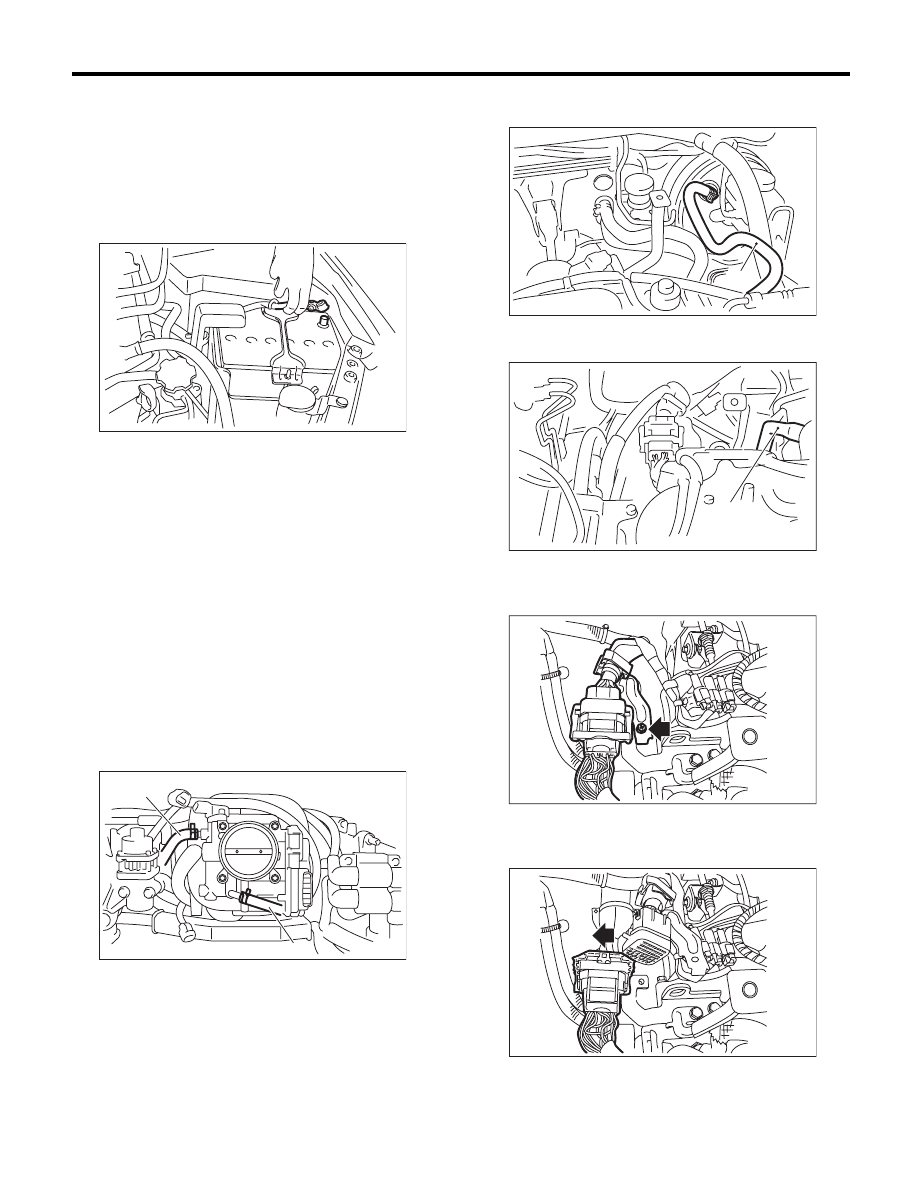
14) Remove the bolt, and disconnect the bulk head
harness connector from the engine harness con-
nector and rear engine hanger.

15) Slide the engine harness connector in the di-
rection of the arrow and remove the rear engine
hanger.

IN-00203

FU-01085

(A)

(A)

FU-02320

(A)

(A)

FU-03956

FU-03924

FU-03925

FU(H4SO)-14

Intake Manifold

FUEL INJECTION (FUEL SYSTEMS)

16) Disconnect the connectors from the engine
coolant temperature sensor.

17) Disconnect the knock sensor connector.

18) Disconnect the connector from crankshaft posi-
tion sensor.

19) Disconnect the connector from power steering
pump switch (A).
20) Disconnect the connector from the oil pressure
switch (B).

21) Disconnect the connector from the camshaft
position sensor.

22) Disconnect the front oxygen (A/F) sensor con-
nector (A) and rear oxygen sensor connector (B).

23) Disconnect the connector from the oil switching
solenoid valve.
24) Disconnect the connector from the variable
valve lift diagnosis oil pressure switch.
• LH  side

• RH  side

FU-00055

FU-02713

FU-00056

FU-03251

(B)

(A)

FU-02714

FU-02734

(B)

(A)

FU-02731

FU-02732

FU(H4SO)-15

Intake Manifold

FUEL INJECTION (FUEL SYSTEMS)

25) Disconnect the connector from the oil tempera-
ture sensor.

26) Remove the EGR pipe from intake manifold.

27) Disconnect the fuel hoses from fuel pipe.

(1) Disconnect the quick connector on the fuel
delivery line by pushing the ST in the direction
of the arrow.

ST

42099AE000

QUICK CONNECTOR 
RELEASE

(2) Remove the clip and disconnect the evapo-
ration hose from the pipe.

CAUTION:
• Be careful not to spill fuel.
• Catch the fuel from hoses using a container
or cloth.

28) Remove the bolts which secure intake manifold
to cylinder head.

29) Remove the intake manifold.

B: INSTALLATION

1) Install the intake manifold onto cylinder heads.

NOTE:
Use a new gasket.

Tightening torque:

25 N·m (2.5 kgf-m, 18.4 ft-lb)

2) Connect the fuel delivery hose and evaporation
hose to the fuel pipe. <Ref. to FU(H4SO)-66, IN-
STALLATION, Fuel Delivery and Evaporation
Lines.>

NOTE:
If fuel hoses or clamps are damaged, replace them
with new parts.
3) Install the EGR pipe to intake manifold.

Tightening torque:

34 N·m (3.5 kgf-m, 25.1 ft-lb)

FU-02733

FU-02974

FU-02866

ST

FU-03252

FU-03252

FU-02974

FU(H4SO)-16

Intake Manifold

FUEL INJECTION (FUEL SYSTEMS)

4) Connect the connector to the oil temperature
sensor.

5) Connect the connector to the variable valve lift
diagnosis oil pressure switch.
• LH  side

• RH side

6) Connect the connector to the oil switching sole-
noid valve.
7) Connect the front oxygen (A/F) sensor connec-
tor (A) and rear oxygen sensor connector (B).

8) Connect the connectors to camshaft position
sensor.

9) Connect the connector to the power steering
pump switch (A).
10) Connect the connector to the oil pressure
switch (B).

11) Connect the connector to crankshaft position
sensor.

12) Connect the knock sensor connector.

FU-02733

FU-02731

FU-02732

FU-02734

(B)

(A)

FU-02714

FU-03251

(B)

(A)

FU-00056

FU-02713


Content   ..  29  30  31  32   ..