SsangYong Rexton. Manual - part 676
SSANGYONG Y200
9D-18 BODY ELECTRICAL
YAD9D260
YAD9D270
YAD9D280
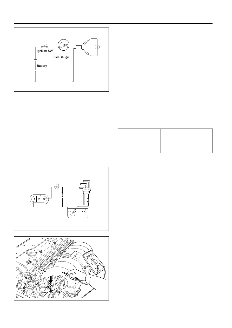
Fuel System
Gauge of fuel
1. Separate connector of fuel sender.
2. Ground connector (B11, B14) of direction of
harness through bulb (12 V, 3.4 W).
3. Turn the start switch on.
4. See if bulb of testing turn on, and see if indicator
of fuel gauge gradually move to position of ‘F’.
Check resistence of fuel sender
1. Put float on the position of ‘F’ and ‘E’, and check
resistence between B11 and B14.
2. While float is moving from position of ‘E’ to
position of ‘F’, check if resistence change
gradually.
Position of float
E
1/2
F
Specified resistence
approximately 285
Ω
approximately 101.5
Ω
approximately 40
Ω
Fuel sender
1. Connect testing bulb (12 V. 3.4 W) of fuel gauge
terminal deepen thermister in the water.
2. See if thermister is deepened in the water, light is
off, and see if thermister get out of water, light is
on.
Notice:
•
If malfunction may happen, replace fuel sender
assembly.
•
After this testing have done, before fuel sender
i s i n s t a l l e d , f u e l s e n d e r s h o u l d d r y u p
completely.
Gauge of Temp
1. Separate wiring connector of water coolant in the
engine room.
2. Ground between testing bulb (12 V,3.4 W) and
connector to harness in a series.
3. Turn ignition switch on.
4. See if testing light turns on or not, check if gauge
of water temp operate or not.