SsangYong Rexton. Manual - part 518


  Index      SsangYong     SsangYong Rexton - service repair manual


Search            


Content   ..  516  517  518  519   ..


SsangYong Rexton. Manual - part 518


SSANGYONG  Y200

4E-36  ABS AND TCS

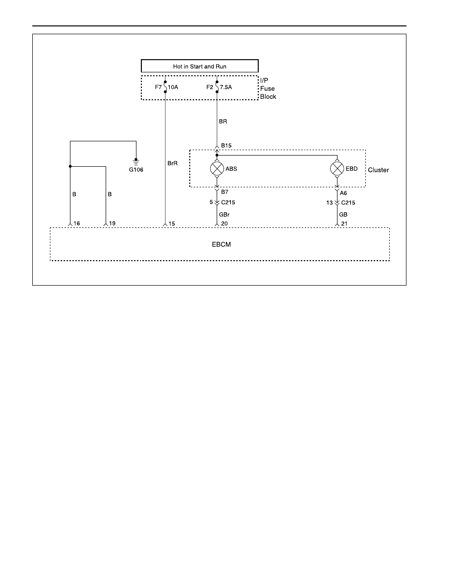
ABS INDICATOR LAMP ILLUMINATED CONTINUOUSLY, NO DTCS

STORED

YAD4E150

Circuit Description

Battery voltage is supplied to the ABS warning lamp
with the ignition in ON or START. The warning lamp
should be activated only by the ABS control module
internally supplying ground to terminal 20.

Diagnosis

This procedure checks for a short to ground in the
wiring or a defective electronic brake control module
(EBCM).

Cause

There is a short to ground in the circuit between the
cluster terminal D7 and the EBCM terminal 31.

The EBCM is faulty.

ABS AND TCS  4E-37

SSANGYONG  Y200

Check the EBCM connector.

Is it connected properly?
Connect the EBCM connector.

Is the repair complete?

1. Disconnect the EBCM connector.
2. Turn the ignition to ON.

3. Use an insulated tool to push the shorting bar in

the connector away from terminal 20.

Does the ABS indicator lamp go out?

Replace the ABS unit

Is the repair complete?
Repair the short to ground in circuit Lg between I/P
cluster connector B7 and terminal 20 EBCM.

Is the repair complete?

ABS Indicator Lamp Illuminated Continuously, No DTCs Stored

Step

1

Action

Yes

No

Value

2

3

Go to Step 4

Go to Step 5

-

4

5

System OK

-

-

System OK

-

-

Go to Step 3

Go to Step 2

-

System OK

-

-

SSANGYONG  Y200

4E-38  ABS AND TCS

SELF-DIAGNOSTICS

Important: The electronic brake control module (EBCM)
turns the valve relay off when a diagnostic trouble code
(DTC) is set. The scan tool will indicate that the valve
relay is off when it is used to monitor the data list. This
is normal and should not be considered a malfunction.

The EBCM performs system self-diagnostics and can
detect and often isolate system malfunctions, When it
detects a malfunction, the EBCM sets a DTC that
represents the malfunction, turns on the ABS and/or
the TCS indicators in most instances, and may disable
the ABS and/or the TCS function, as necessary, for
the duration of the ignition cycle.

Once each ignition cycle, the EBCM performs an
automatic test when the vehicle reaches 2.75 km/h (1.7
mph). In the course of this test, the system cycles
each valve solenoid and the pump motor, along with
the necessary relays, to check component operation.
If the EBCM detects any malfunctions, it will set a
DTC as described above.

DISPLAYING DTCs

Tools Required

Scan Tool

DTCs can be read through the use of the scan tool.

CLEARING DTCs

Tool Required

Scan Tool

The diagnostic trouble codes (DTCs) in the electronic
brake control module (EBCM) memory are erased in
one of two ways:

Use the scan tool “Clear DTCs” selection.

After 249 DTC-free ignition cycles.

These two methods are detailed below. Be sure to
verify the proper system operation and, the absence
of DTCs when the clearing procedure is completed.

The EBCM will not permit DTC clearing until all DTCs
have been displayed. Also, ETC s cannot be cleared
by disconnecting the EBCM, disconnecting the battery
cables, or turning the ignition switch to LOCK.

Scan Tool Method

The scan tool can clear ABS/TCS system DTCs using
the mess storage cartridge.

1. Install the scan tool and the mass storage cartridge.

2. Select “Fault Memory”.

3. Select “Clear Fault Memory”.

Clearing the fault memory cannot reset a valve relay
which was shut down when the fault was recognized.
Changes are possible only after the fault has been
eliminated and the next ignition cycle has begun.

Ignition Cycle Default

A DTC is erased from memory after 249 ignition cycles
without any reappearance of that malfunction.

INTERMITTENT AND POOR
CONNECTIONS

As with most electronic systems, intermittent
malfunctions may be difficult to diagnose accurately,
The following is a method to try to isolate an intermittent
malfunction, especially in wheel speed circuitry.

If an ABS malfunction occurs, the ABS indicator will
illuminate during the ignition cycle in which the
malfunction was detected. If it is an intermittent
problem which seems to have corrected itself (ABS
indicator OFF), a history DTC will be stored. Also stored
will be the history data of the DTC at the time the
malfunction occurred. Use the scan tool modular
diagnostic system to read ABS history data.

Most intermittents are caused by faulty electrical
connections or wiring, although a sticking relay or
solenoid can occasionally be at fault.

SSANGYONG  Y200

4E-40  ABS AND TCS

DIAGNOSTIC TROUBLE CODE (DTC) 035 LEFT FRONT WHEEL SPEED

SENSOR FAULT

YAD4E170

Circuit Description

The toothed wheel generates a voltage pulse as it
moves past the sensor. Each tooth-gap-tooth series
on the wheel generates the pulses. The electronic brake
control module (EBCM) uses the frequency of these
pulses to determine the wheel speed. The voltage
generated depends on the air gap between the sensor
and the toothed wheel, and on the wheel speed.

Diagnosis

This procedure checks for a malfunctioning wheel
speed sensor, a short to ground or to voltage in the
wiring, or a contact problem in a connector.

Cause

The wheel speed sensor is defective.

There is a problem in the wiring.

There is a problem with a connector.

Action Taken When the DTC Sets

ABS action is disabled, and the ABS warning lamp is
ON.

Test Description

The number(s) below refer to step(s) on the diagnostic
table.

1. This step begins an examination for a defective

wheel speed sensor.

6. This step tests the wiring for a short to voltage.

8. This step tests the wiring for a short to ground.

10. This step tests for an open or a high resistance in

the wiring.

Diagnostic Aids

Be sure that the speed sensor wiring is properly routed
and retained. This will help to prevent false signals
due to the pickup of electrical noise.

It is very important to perform a thorough inspection
of the wiring and the connectors. Failure to inspect the
wiring and the connectors carefully and completely may
result in misdiagnosis, causing part replacement with
the reappearance of the malfunction.

Use the scan tool to monitor wheel speeds during a
road test. Watch the wheel speeds being displayed
on the scan tool to see if any of the readings are
unusual, such as one sensor varying in speed from
the other three, a signal going intermittently high or
low, etc. If this does not identify the intermittent, wet
the speed sensor harness on the underside of the
vehicle and perform a road test, monitoring wheel
speeds with the scan tools.


Content   ..  516  517  518  519   ..