SsangYong Rexton. Manual - part 389


  Index      SsangYong     SsangYong Rexton - service repair manual


Search            


Content   ..  387  388  389  390   ..


SsangYong Rexton. Manual - part 389


DIESEL ENGINE MECHANICAL  1B3-131

SSANGYONG  Y200

Tools Required

601 589 00 66 00

Counter Sink

607 589 00 23 00

Height Gauge

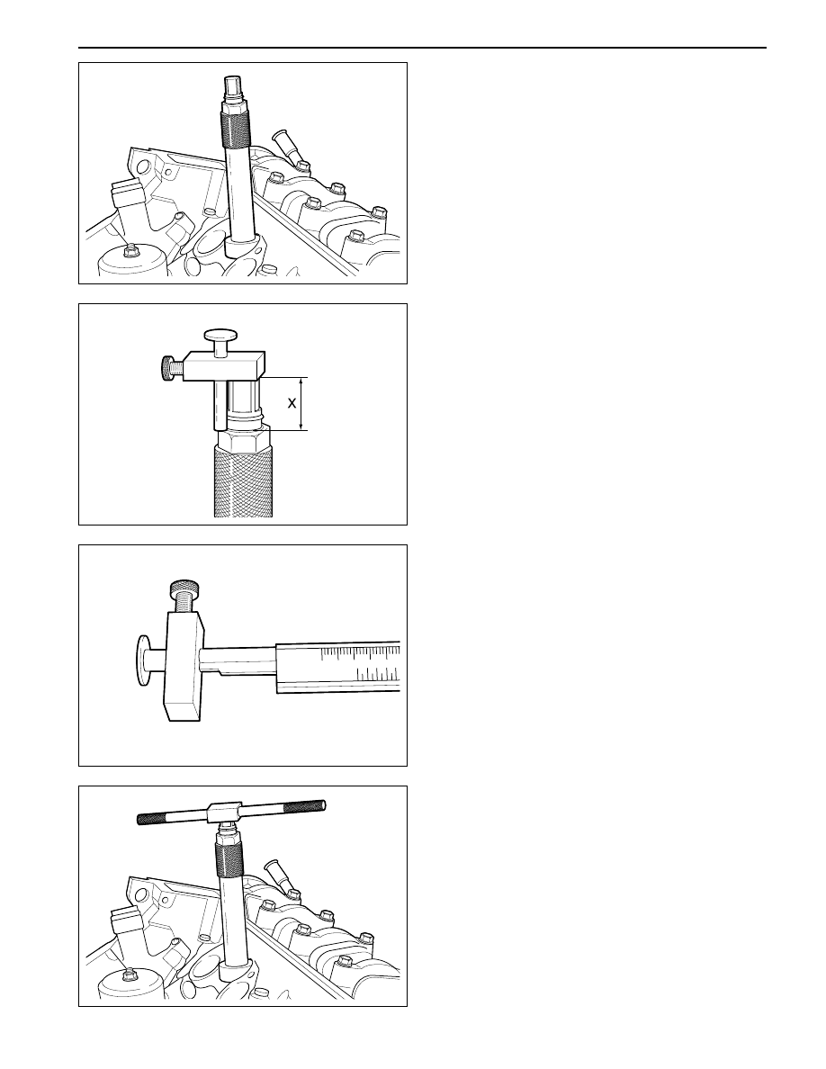
Milling  of the Prechamber Sealing Surface

1. Remove the injection nozzle.

2. Remove the prechamber.

3. Cover the prechamber bore to avoid any chips

dropping into the combustion chamber.

4. Remove the protective sleeve from the counter sink

601 589 00 60 00 and rotate the counter sink 601
589 00 60 00 into the prechamber bore to be
machined as far as the stop.

7. Mount the turning tool onto the counter sink 601

589 00 60 00 and rotate to the right approx. 5
revolutions by applying slight pressure.

6. Measure the ‘X’ by using a vernier caliper.

5. Maintain size ‘X’ from the top edge of mandrel to

the top edge of the sleeve with the height gauge
667 589 00 23 00.

YAD1BJ50

YAD1BJ60

YAD1BJ70

YAD1BJ80

SSANGYONG  Y200

1B3-132  DIESEL ENGINE MECHANICAL

YAD1BJ90

YAD1BJA0

8. Remeasure size ‘X’ and compare it with the first

measurement and determine the thickness of
spacer ring.

12. Punch a mark on the cylinder head above the

prechamber sealing surface which has been
machined.

1 3. Install the prechambers.

Notice:  If the cylinder head is removed, the
projection  ‘C’ is measured in place of size ‘X’
and the appropriate size of spacer ring selected.

The spacer ring should be selected so that it is
at least 0.1 mm and not more than 0.3 mm
thicker than the measured on the sealing
surface. In this example, the necessary
thickness of spacer ring should be within 0.3 ~
0.5 mm and the thickness of spacer ring to be
installed is 0.3 mm.

9. Remove the counter sink 601 589 00 60 00 and

clean the chips.

Notice: If the sealing surface is not completely
flat, remachine the sealing surface.

10. Remove rag from the prechamber bore and crank

the engine with starter motor to threw out any chips
which may have got into the combustion chamber.

11. Insert the proper spacer ring into the prechamber

sealing surface.

Normal Projection (C)

7.6 - 8.1 mm

Size before machining

Size after machining

25.7 mm

25.5 mm

Ex

DIESEL ENGINE MECHANICAL  1B3-133

SSANGYONG  Y200

TDC (TDC SENSOR BRACKET) SETTING

Preceding Work:

Removal of No.1 cylinder prechamber

YAD1BJB0

1 Measuring Device
2 Dial Gauge

3 Cylinder Head
4 Piston ................................................  Set at TDC

Notice:

The TDC sensor bracket must be adjusted in case of followings.

When replacing the TDC sensor bracket.

When replacing the crankshaft, the hub or the vibration  damper.

When replacing or installing the timing case cover.

After engine overhauling.

*

If the cylinder head is removed, the measuring pin of the dial gauge can be positioned on the piston crown.

This is done by placing the magnetic dial holder on the mating surface of the crankcase.

SSANGYONG  Y200

1B3-134  DIESEL ENGINE MECHANICAL

YAD1BC10

YAD1BJC0

YAD1BJD0

Tools Required

001 589 32 21 00

Dial Gauge

601 589 07 21 00

Measuring Device

667 589 01 21 00

Fixing Device

Setting (With Cylinder Head Installed)

1. Remove the prechamber of No. 1 cylinder.

2. Position the piston of No.1 cylinder at BTDC 10° .

3. Install the measuring device 601 589 07 21 00 into

the prechamber bore and position the dial gauge
001 589 53 21 00 with a preload of 5mm.

4. Slowly rotate the crankshaft in the direction of

engine rotation until the large pointer on the dial
gauge 001 589 53 21 00 stops (TDC position).

Notice:  The position of TDC is when the large
pointer on the dial gauge is stopped before moving
back.

5. Remove the reinstall the measuring device and

position the dial gauge 001 589 53 21 00 scale at ‘0’.

6. Slowly rotate the crankshaft in the direction of

engine rotation until the dial gauge 001 589 53 21
00 has moved back (counterclockwise) by 3.65
mm.

7. Insert fixing device into the sensor bracket.

Notice: The pin (6) on the vibration damper must
engage into the slot of the fixing device 667 589
01 21 00 (7).

8. If the pin does not engage, adjust the setting of

the sensor bracket by removing and tightening of
the sensor bracket bolts.

Installation Notice

The timing mark on the damper must be positioned
at ATDC 20° .

Tightening Torque

10 N•m (89 lb-in)


Content   ..  387  388  389  390   ..