SsangYong Rexton. Manual - part 20
DI01-34
CHANGED BY
EFFECTIVE DATE
AFFECTED VIN
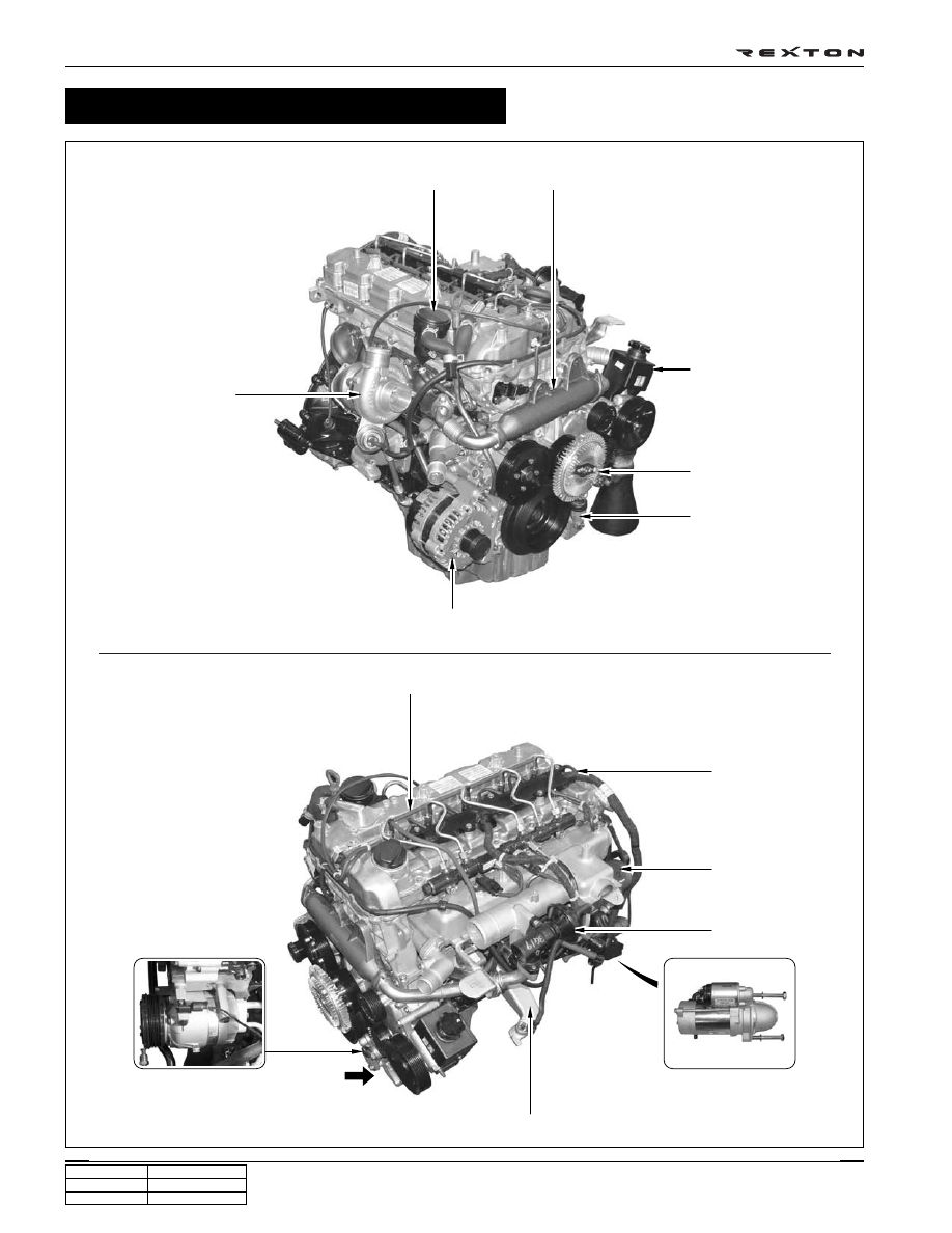
ENGINE ASSEMBLY
DI ENG SM - 2004.4
Y220_01048
Accessories - Removal and Installation
PCV valve and oil separator
EGR valve pipe (LH, Center, RH)
Power steering pump
Cooling fan clutch
Auto tensioner
Alternator
Turbo charger
Fuel return hose
Cable and connector
Oil filter assembly
EGR valve
Start motor
Mounting bracket
Air conditioner compressor