SsangYong Stavic / SsangYong Rodius (2005 year). Manual - part 408
ABS/ESP SYSTEM
STAVIC - 2004.09
15
4K
CHANGED BY
EFFECTIVE DATE
AFFECTED VIN
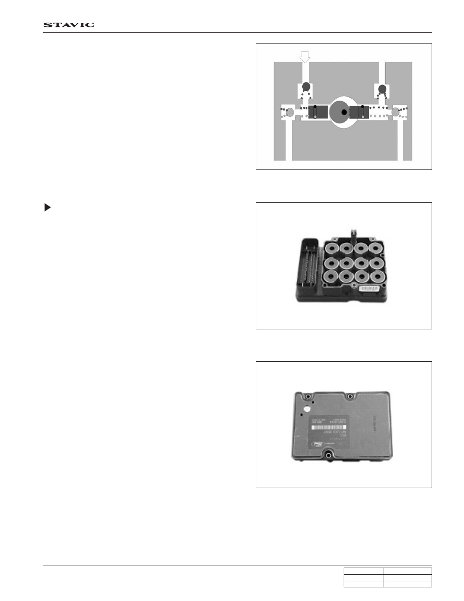
(Pumping)
When the cam pushes the left plunger during motor operation,
the system pressure is generated in the left cylinder. At this
time, the right plunger is expanded by spring force and the
expanded volume of the right cylinder draws the brake fluid.
ECU (Including Solenoid Valves –
ESP Equipped Model)
HECU controls the hydraulic valves by supplying or cutting off
the voltage to solenoid valves depending on the wheel speed
and other information from wheel speed sensors.
The figure shown in left side is for ESP ECU. There are two
channels for front wheels and one channel for rear wheels.
Each channel has one inlet and one outlet valve, therefore,
there are six solenoid valves.
(ECU lower cover)
The electrical components are weak to moisture. To protect
ECU, GoreTex-based plate is used at ECU lower cover. The
vent hall (arrow) allows air to ventilate but does not allow mois-
ture to penetrate.