SsangYong Stavic / SsangYong Rodius (2005 year). Manual - part 307


  Index      SsangYong     SsangYong Stavic / SsangYong Rodius - service repair manual 2005 year


Search            


Content   ..  305  306  307  308   ..


SsangYong Stavic / SsangYong Rodius (2005 year). Manual - part 307


CHANGED BY

EFFECTIVE DATE

AFFECTED VIN

42

DC 5-SPEED AUTOMATIC TRANSMISSION

STAVIC - 2004.09

4A

Self diagnostic 11

Selector lever unit

Instrument panel

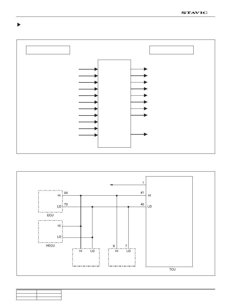
CAN (Controller Area Network )

Function

Circuit diagram

CAN input signal

CAN output signal

TCU

Accelerator pedal position

Wheel speed (all wheels)

Engine rpm, Engine torque

Coolant temperature

Downshift

Speed control (constant)

Meshed gear

2nd gear start up control

Selected gear in transfer case

Selector lever position

Odometer (I/P)

Selected gear

Shifted status

Lock-up clutch status

Automatic transmission

Kick-down status

Driving conditions

Engine torque control

Dangerous status (changes to
emergency mode when
overloading, dangerous conditions,
and internal fault exists)

ATF Temperature

CHANGED BY

EFFECTIVE DATE

AFFECTED VIN

43

DC 5-SPEED AUTOMATIC TRANSMISSION

STAVIC - 2004.09

4A

Function

TCU controls the gear groups according to the driving conditions. It receives the driving data from many sensors and
switches as input signals. It is also connected with ECU, HECU, instrument panel and selector lever control unit.

1. Shifting Method

Basic shift operation includes up-shift and down-shift for all gear groups. Shift control unit determines driving
resistance, accelerator pedal position, vehicle speed and some parameters (road surface condition, up hill and
down hill gradients, trailer driving conditions, catalytic converter conditions, driving habits and automatic transmission
oil temperature) to select a shift gear.

2. Down Shift

When engine speed increases excessively, the down shift does not occur.

3. Engine RPM Adjustment

During shifting, the engine torque is reduced to optimize the shift operation by delaying the ignition time.

4. Lock-Up Clutch Control

The lockup clutch in torque converter is activated in 3rd, 4th and 5th gear and operates in sequence via PWM
solenoid valve.

5. Others

The transmission is automatically controlled to compensate durability and wear.

The shift control values such as shifting point, shifting time, pressure during shifting, and lockup clutch control are
permanently saved and the diagnosis is partially available.

TCU (Transmission Control Unit)

TCCU

TCU

CHANGED BY

EFFECTIVE DATE

AFFECTED VIN

44

DC 5-SPEED AUTOMATIC TRANSMISSION

STAVIC - 2004.09

4A

TCU block diagram

Engine

control

Engine torque

Max. Engine torque

Engine power loss

Engine rpm

ACC pedal position

Engine torque

reduction

Engine control status

HECU

Wheel speed (FR, FL)

Wheel speed (RR, RL)

Shift pattern changes

Driving force control

Selector

angle

Posi. Identifi. signal WO

Posi. Identifi. signal W1

Posi. Identifi. signal W2

Posi. Identifi. signal W3

W/S mode signal input

I/P

Selector lever indication

Part-

time

TOD

TCCU

Selected T/C gear

Sol.

valve

M/P S/V

S/P S/V

Power supply (valves)

1-2/4-5 gears S/V

3-4 gears S/V

2-3 gears S/V

Sensor

Sensor power supply

Sensor fround

Starter

relay

Start signal

T/M

Diag.

Conn.

Lockup clutch S/V

N3 speed

Shift pattern changes

Driving force controls

N2 speed

Diagnosis

IGN1

P/N starting recognition

TCU (EGS) power

Power

ground

TCU (EGS) ground

T

C

U

C

A

N

D

I

G

I

T

A

L

36

37

38

14

15

16

17

13

33

7

12

35

1

29

25, 27

30

Mileage

W/S mode indication

Shift pattern changes

CHANGED BY

EFFECTIVE DATE

AFFECTED VIN

45

DC 5-SPEED AUTOMATIC TRANSMISSION

STAVIC - 2004.09

4A

Characteristics of TCU and Automatic Transmission (LHM: Limp-Home
Mode)

The emergency driving mode is to minimize vehicle’s operation when is a mode for maintaining minimum driving condi-
tion when the automatic transmission is defective. In emergency driving mode, excessively long driving and unreason-
able driving should be avoided to prevent bigger fault occurring in advance. Emergency driving mode can largely be
divided in electrical defective and hydraulic pressure/mechanical defective.

Electrical defect

• If an electrical defective occurs in transmission during driving, current shift gear position is held.

A. Shut off of various solenoid valves

B. Internal pressure in transmission increases (shift shock gets bigger when changing selector lever due to

maximized MP and SP)

C. Lockup clutch is released

• If the shift operation cannot be activated, the driver must reset the system as follows:

A. Stop the vehicle and place the selector lever to “P” position.

B. Wait for 10 seconds after stopping the engine (release hydraulic pressure)

C. Start the engine.

D. Place the selector lever to “D” or “R” position.

Mechanical/hydraulic pressure defect

• Characteristics that appears in the vehicle are as below:

A. Holds at 3rd gear (It can be held at proper gear if the fault occurs at 3rd gear)

B. Electrical devices operate normally and the shift shock is acceptable during shift operation.

• If the shift operation cannot be activated, the driver must reset the system as follows:

A. Stop the vehicle.

B. Put the selector lever in “P” or “N” position.

C. Stop the engine.

D. In most cases, it is reset when the engine is started and the vehicle operate normally.

If, however, hydraulic or mechanical problem is not cleared, shifting is hold in 3rd or most stable gear range.


Content   ..  305  306  307  308   ..