SsangYong Stavic / SsangYong Rodius (2005 year). Manual - part 294


  Index      SsangYong     SsangYong Stavic / SsangYong Rodius - service repair manual 2005 year


Search            


Content   ..  292  293  294  295   ..


SsangYong Stavic / SsangYong Rodius (2005 year). Manual - part 294


CHANGED BY

EFFECTIVE DATE

AFFECTED VIN

24

FFH & PTC

STAVIC - 2004.09

3B

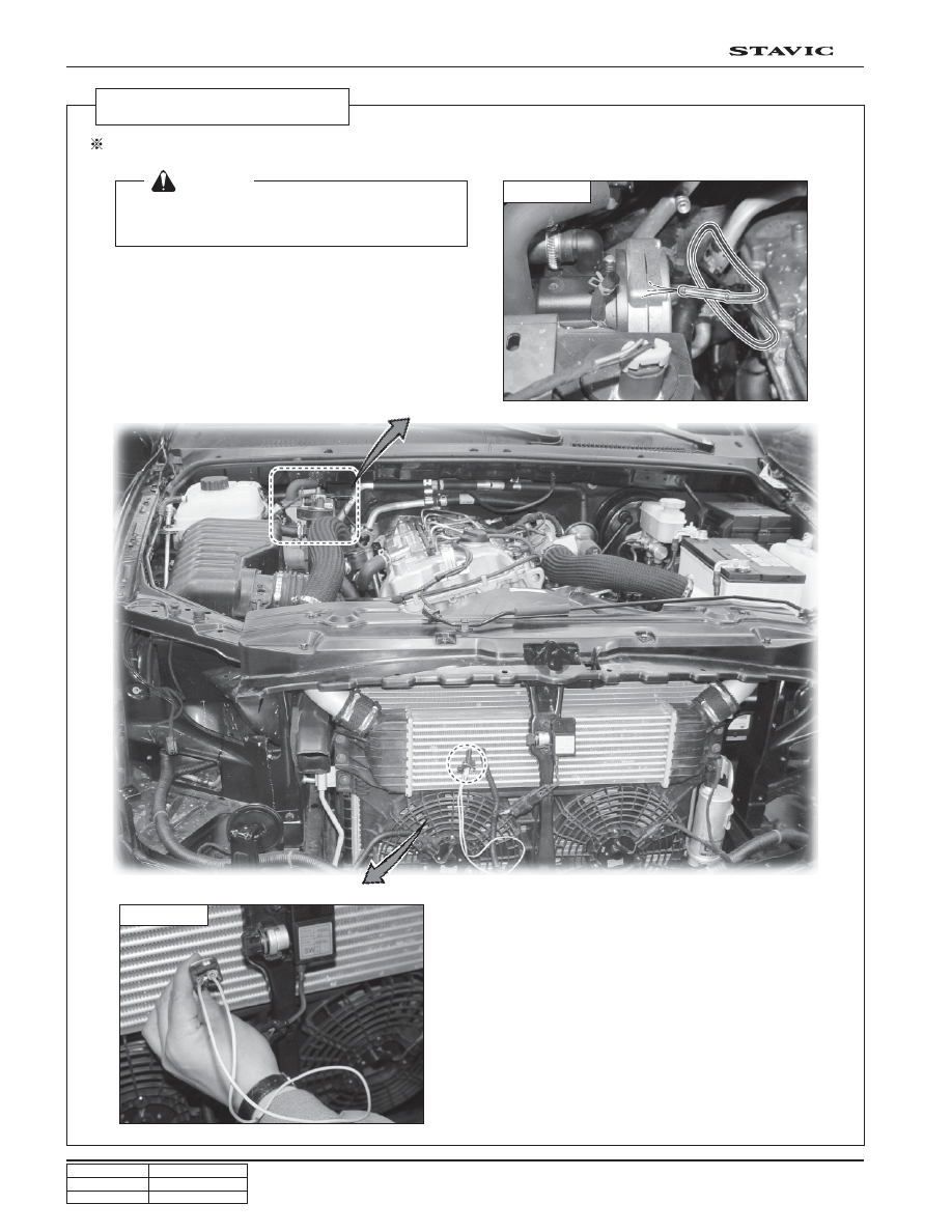
Fuel Feeding Process

Fuel Feeding job should be followed after changing FFH assy or after fuel line job.

 [Notice]

Without feeding job, FFH system could make white
smoke with abnormal noise.

3. If the fuel is sprayed out, connect the fuel pipe to

FFH assembly and keep the engine running for
1 minute.

4. Connect the ambient temperature connector.

1. Disconnect the ambient temperature switch as

shown in picture (A).

2. Check if the fuel comes out after engine starting

as the FFH fuel supply hose is disconnected.
(Picture B)

Picture B

Picture A

CHANGED BY

EFFECTIVE DATE

AFFECTED VIN

25

FFH & PTC

STAVIC - 2004.09

3B

Controller Lock

• The controller is locked when the following faults occur:

Overheating

• If FFH overheats 10 times in succession, error code 015 appears and the controller is locked.

Too many start attempts

If FFH performs 10 start attempts in vain, error code 050 appears and the controller is locked.

8. TROUBLE DIAGNOSIS

1. FFH Heater Trouble Diagnosis Precedure

When Faults Occur, First Check…

• Faulty wiring?

(short circuits, interruptions)

• Visual check for

- corroded contacts
- defect fuses
- damaged electrical leads, links and connections
- damaged exhaust and combustion air guidance

• Check battery voltage

Battery voltage < 10 volt: the undervoltage protection has triggered

• Check fuel supply

Check Voltage Supply U

batt

 (terminal 30)

Disconnect the 10-pin connector and measure the voltage present in connector between chamber 1 and chamber 2.

For deviations in the battery voltage, check the fuses, supply lines, ground connection and plus point on battery for loss
of voltage (corrosion / interruption).

Check Key-ON signal (D+)

Disconnect the 10-pin connector and measure the voltage present in connector 1 between chamber 6 and chamber 2.

 [Notice]

Heater operating conditions

Ambient temperature: below 5°C

Engine coolant temperature: below 75°C

CHANGED BY

EFFECTIVE DATE

AFFECTED VIN

26

FFH & PTC

STAVIC - 2004.09

3B

1. Vehicle

2. Choose No.11 item FFH

SCAN100 Diagnosis

3. Choose trouble code checking.

CHANGED BY

EFFECTIVE DATE

AFFECTED VIN

27

FFH & PTC

STAVIC - 2004.09

3B

No faults

Shutdown for overvoltage

Shutdown for undervoltage

Overheating (software threshold)

Overheating (difference evaluation)

Overheating (operating block)

Difference evaluation 2

Overheating (hardware, device)

Glow plug interruption

Overload, short-circuit or ground
contact, glow plug output

Glow plug output defect

Comunication line short

• Measure battery voltage (must be < 15.9V)

• Check alternator

• Check alternator over voltage

• Measure battery voltage (must be > 10.2V under load)

• Check alternator

• Check lead

Temperature at overheating sensor >125°C

• Check cooling system:

• Check the temperature sensor and overheating sensor, replace

if necessary

Difference in temperature values between surface sensor and con-
trol overheating sensor is too large. (Prerequisite for this trouble
code display is that the heater is in operation and the water tem-
perature at the overheating sensor has reached min. 80°C)

• Check cooling system

• Check the temperature sensor and overheating sensor, replace

if necessary

The controller is locked.

• Delete the fault memory to release the controller

• Check cooling system

• Check the temperature sensor and overheating sensor, replace

if necessary

If the surface sensor has a far higher temperature value than the con-
trol overheating sensor, then the system proceeds with a fault shutdown.

Temperature at control overheating sensor > 125°C

• Check cooling system

• Check the temperature sensor and overheating sensor,replace

if necessary

• Check cable harness for this component for damage and

through current and replace component if necessary

• Check plug-in connection, replace component if necessary

• Check cable harness for this component for damage, replace

component if necessary

• Check cable harness for this component for damage, replace

component if necessary

• Check the line

DTC (Diagnosis Trouble Code)

Remedies

Trouble Description

Trouble

Code

0

10

11

12

14

15

16

17

20

21

22

25


Content   ..  292  293  294  295   ..