SsangYong Korando II (1996-2006 year). Manual - part 246
SSANGYONG MY2002
4E-22 REAR BRAKES
UNIT REPAIR
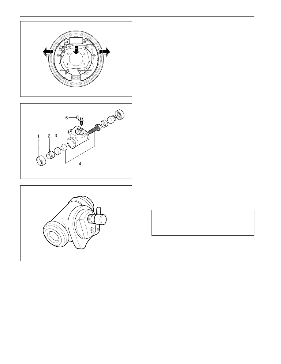
WHEEL CYLINDER
Disassembly Procedure
1. Remove the upper brake return spring and remove
the wheel cylinder with pulling the upper lining
outside.
2. Disassembly the wheel cylinder assembly.
•
Remove the dust boot and do not reuse them
(1).
•
Remove the piston (2).
•
Remove the piston cup and do not reuse it (3).
•
Remove the spring assembly (4).
•
Remove the bleeder screw (5).
3. Clean all the parts with the denatured alcohol. Dry
the parts with unlubricated compressed air.
Bleeder Screw
7 - 10 N•m
(62 - 89 lb-in)
8 - 12 N•m
(71 - 106 lb-in)
Wheel Cylinder
Mounting Bolt
Notice: Lubricate the new seals, the piston, the
piston cup and the wheel cylinder bore with clean
brake fluid before assembly.
4. Installation should follow the removal procedure
in the reverse order.
5. Tighten the bleeder screw and wheel cylinder as
specified torque.
YAD4C460
YAD4C470
YAD4C480