SsangYong Korando II (1996-2006 year). Manual - part 207
WHEEL ALIGNMENT 2B-7
SSANGYONG MY2002
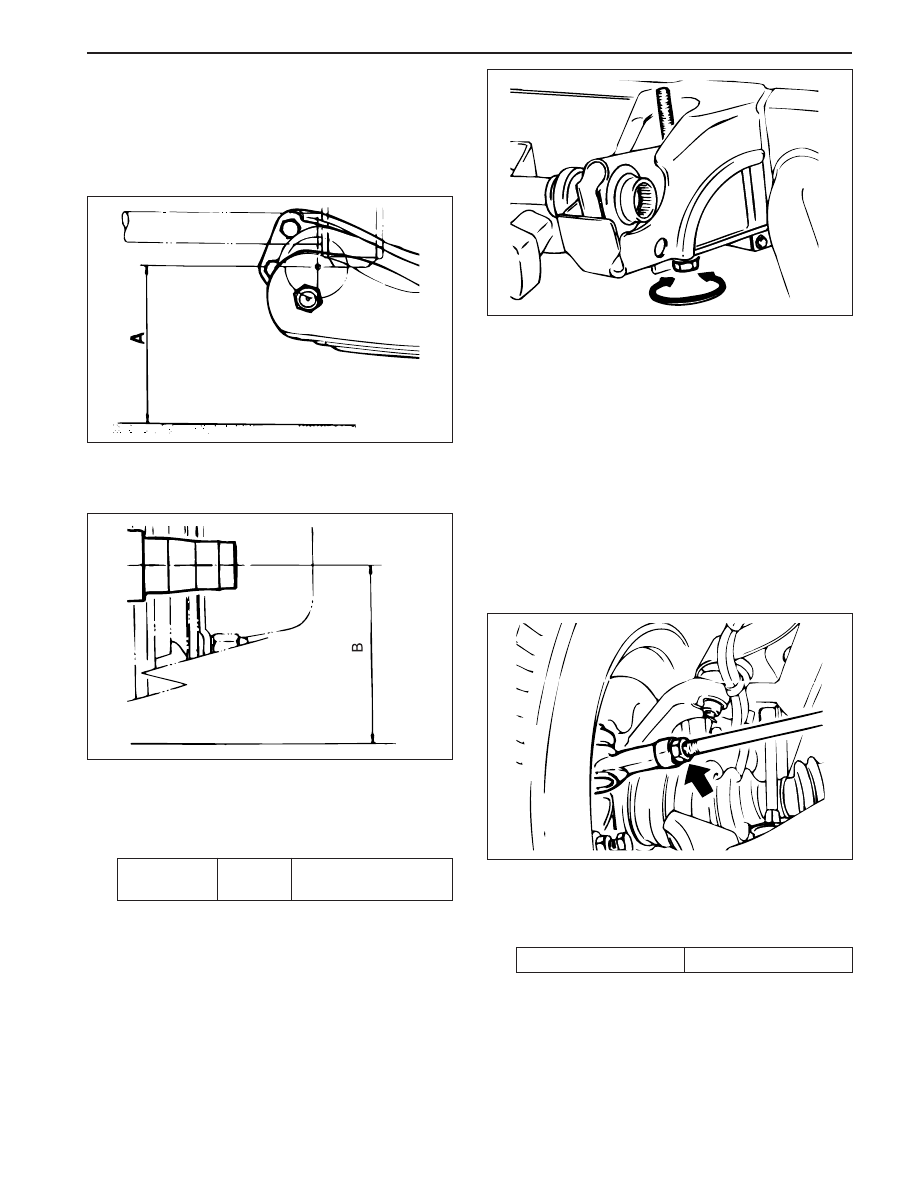
VEHICLE HEIGHT
Adjustment Procedure
1. Check the tire for proper inflation.
2. Measure ‘A’ from the center of the lower arm
rear mounting bolt end to the ground.
KAA2B050
3. Measure ‘B’ from the center of the steering
knuckle shaft to the ground.
KAA2B060
4. If the difference between ‘A’ and ‘B’ is not
within specification, adjust vehicle height using
torsion bar height control bolt.
Adjustment Notice
Specification
31 - 36 mm
(1.22 - 1.42 inch)
B - A
Notice: Before wheel alignment, adjust vehicle
height adjustment first.
KAA2B070
FRONT TOE-IN ADJUSTMENT
Adjustment Procedure
1. Disconnect the outer tie rods from the knuckle as-
semblies. Refer to Section 6C, Power Steering
Gear.
2. Loosen the front toe adjusting nut.
Notice: In this adjustment, the right and the left tie
rods must be equal in length, or the tires will wear
unevenly.
3. Turn the right and the left outer tie rods to align the
toe to the proper specifications. Refer to “Wheel
Alignment Specifications” in this section.
KAA2B080
4. Hold the outer tie rod and tighten the front toe adjust-
ing nut.
Adjustment Notice
Tightening Torque
73 N•m (54 lb-ft)
5. Reconnect the outer tie rods to the knuckle assem-
blies. Refer to Section 6C, Power Steering Gear.