SsangYong Korando II (1996-2006 year). Manual - part 164
OM600 ENGINE MECHANICAL 1B3 -- 105
DAEWOO MY_2000
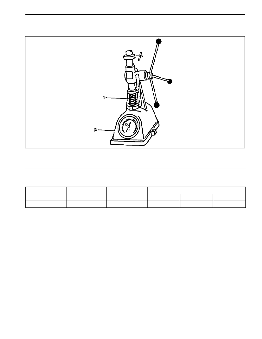
VALVE SPRINGS CHECK
Preceding Work : Removal of valve spring
1 Valve Spring
2 Spring Scale
Service Data
Outer diameter
Wire diameter
Free length
At preloaded
Outer diameter
Wire diameter
Free length
Length
Tension (new)
Limit
33.1 mm
4.20 mm
50.0 mm
27 mm
680 -- 740 N
612 N