Skoda Yeti (2017 year). Manual - part 10


  Index      Skoda     Skoda Yeti (2017 year) - manual in english


Search            copyright infringement  


Content      ..     8      9      10      11     ..


Skoda Yeti (2017 year). Manual - part 10


The speed limit for all-season or “winter”Tires can be adjusted in MAXI
DOTDisplay in the menu item winter tires 

» page 43

.

If the vehicle has all-season or “winter”tires of a lower speed category then
the specified maximum speed of the vehicle (referring to tyres that have not
been delivered by the factory, a warning label with the maximum value of the
speed category provided for the mounted tyres must be fixed in the interior of
the vehicle in a constantly visible place in the driver’s field of vision. The warn-
ing label (sticker) can be replaced by setting maximum value of the mounted
tire speed rating in the MAXI DOTDisplay in thewinter tiresmenu item

1)

. This

specification defines the maximum vehicle speed with mounted all-season or
“winter”tyres that may not be exceeded.

Snow chains

The snow chains improve handling in wintry road conditions.
Remove the full wheel trims before installing the snow chains 

» page 156

.

Only fit snow chains with links and locks not larger than 12 mm.
The use of snow chains on vehicles with front-wheel drive and on vehicles
with four-wheel drive differs.

Front-wheel drive
Snow chains must only be fitted on the front wheels and are applicable only to
the following wheel / tyre combinations.

Rim size

Press depth D

Tyre size

6J x 16

50 mm

205/55 R16

7J x 16

45 mm

205/55 R16

6J x 17

45 mm

205/50 R17

All-wheel drive
Snow chains can be mounted on the wheels on the front and rear axles.
It is only permissible to fit snow chains on the front wheels with the following
wheel/tyre combinations.

Rim size

Press depth D

Tyre size

6J x 16

50 mm

205/55 R16

7J x 16

45 mm

205/55 R16

6J x 17

45 mm

205/50 R17

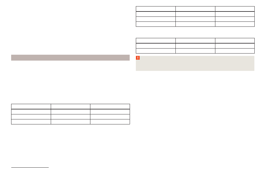
It is only permissible to fit snow chains on the rear wheels with the following
wheel/tyre combinations.

Rim size

Press depth D

Tyre size

7J x 16

45 mm

215/60 R16

7J x 17

45 mm

225/50 R17

WARNING

Do not use chains on snow and ice-free routes - the handling would be im-
paired and there is a risk of damage to the tyres.

1)

Valid in certain countries.

153

Wheels

-------------------------------------------------------------------------------------------------------------------------------------------------------------

Do-it-yourself

Emergency equipment and self-help

Emergency equipment

Introduction

This chapter contains information on the following subjects:
Placement of the first aid kit and warning triangle

154

Location of reflective vest

154

Fire extinguisher

154

Vehicle tool kit

155

Placement of the first aid kit and warning triangle

Fig. 167  Location of the first-aid kit and the warning triangle

The following information applies for the first aid kit and warning triangle from
the ŠKODA Original Accessories.

Placing the first-aid kit
The first-aid box can be attached by a strap to the right-hand side of the boot

» Fig. 167

 - .

Placing of the warning triangle
The warning triangle can be attached using the tensioning straps in the recess
of the loading edge 

» Fig. 167

 - .

The warning triangle, which is included in the equipment with the spare wheel,
can be stowed in a removable box on the right next to the spare wheel

» page 91

.

WARNING

Properly secure the first aid kit and the warning triangle - there is a risk of
injury in the event of sudden braking or a vehicle collision.

Location of reflective vest

Fig. 168 
Storage compartment for the re-
flective vest

The reflective vest can be stowed in a holder under the driver's seat 

» Fig. 168

.

Fire extinguisher

Fig. 169 
Release the fire extinguisher

The fire extinguisher is attached by two straps in a holder underneath the driv-
er's seat.

To remove the fire extinguisher, release the safety catches on the two belts
in the direction of arrow 

» Fig. 169

 and remove the fire extinguisher.

To secure, place the fire extinguisher back in the mount and secure with the
belts.

The Owner's Manual is fitted next to the fire extinguisher.
Pay attention to the expiration date of the fire extinguisher. After this date,
the correct function of the device is not guaranteed.

154

Do-it-yourself

-------------------------------------------------------------------------------------------------------------------------------------------------------------

WARNING

Always properly secure the fire extinguisher - there is a risk of injury in the
event of sudden braking or a vehicle collision.

Vehicle tool kit

Fig. 170  Vehicle tool kit

The box containing the vehicle tool kit is located in the storage compartment
for the spare wheel, and can be secured with a tape depending on the equip-
ment fitted.
Depending on the vehicle configuration, it may not contain all the compo-
nents listed in the on-board tool kit.

Screwdriver
Key for removing and installing the tail light
Top section for the anti-theft wheel bolts
Towing eye
Clamps for removing the wheel trims
Jack with sign
Wheel wrench
Extraction pliers for the wheel bolt caps
Breakdown kit

1

2
3
4
5
6
7
8
9

WARNING

The factory-supplied lifting jack is only intended for your model of vehicle.

Under no circumstances attempt to lift other vehicles or loads with it –
there is a risk of injury.

Always securely stow the tool in the box and make sure that it is secured

to the spare wheel using the tape - Otherwise there is a risk of injury in the
event of sudden braking or a vehicle collision.

CAUTION

Screw the jack back to its starting position prior to putting it back in its box -
There is a risk of damage to the box.

Note

The declaration of conformity is included with the jack or the log folder.

Changing a wheel

Preliminary work

For safety's sake, the following instructions must be observed before
changing a wheel on the road.

Park the vehicle as far as possible away from the traffic flow - choose a place
with a flat and firm surface.

Switch off the engine.

For vehicles with manual transmission, select 1 gear.

For vehicles with automatic transmission, place the selector lever in the P
position.

Firmly apply the handbrake.

Switch on the hazard warning lights and set up the warning triangle at the
prescribed distance.

Have all the occupants get out. The passengers should not stand on the
road while the wheel is being changed (they should remain behind a crash
barrier, for instance).

Uncouple any trailers.

Changing a wheel

Remove the spare wheel 

» page 156

.

Remove the full wheel trim 

» page 156

 or caps 

» page 157

.

Loosen the wheel bolts 

» page 158


» 

.

155

Emergency equipment and self-help

-------------------------------------------------------------------------------------------------------------------------------------------------------------

Jack up the vehicle

» page 158

 until the wheel that needs changing is clear of

the ground.

Unscrew the wheel bolts and place them on a clean surface (cloth, paper,
etc.).

Remove the wheel carefully.

Attach the spare wheel and slightly screw on the wheel bolts.

Lower the vehicle.

Tighten the wheel bolts opposite each other using the wheel wrench (“pull-
ing crossways”)

» page 158

.

Replace the wheel trim 

» page 156

 and caps 

» page 157

.

When fitting unidirectional tyres, ensure that the direction of rotation is cor-
rect 

» page 150

.

All bolts must be clean and must turn easily. If screws are corroded and diffi-
cult to move, these must be replaced.

WARNING

Undo the wheel bolts just a little (about one turn), provided the vehicle

has not yet been jacked up. Otherwise the wheel could come loose and fall
off – risk of injury.

Under no circumstances must the bolts be greased or oiled - cause an ac-

cident.

Subsequent steps

After changing the wheel, the following work must be carried out.

Stow the replaced wheel in the well under the floor covering of the luggage
compartment and secure with a locking screw.

Stow the vehicle tool kit in the space provided.

Check tyre pressure on the mounted wheel and adjust if necessary and, with
vehicles with tyre pressure monitoring, save the tyre pressure values in the
system 

» page 123

.

Have the tightening torque of the wheel bolts checked as soon as possible.
The prescribed tightening torque is 120 Nm.

Replace the damaged wheel or consult a specialist garage about repair op-
tions.

WARNING

Tightening torque which is too high can damage the threads and this can
result in permanent deformation of the contact surfaces on the rim. Where
tightening torque is too low, the wheels may become loose while driving -
There is a risk of an accident. Therefore drive cautiously and only at a mod-
erate speed until the tightening torque has been checked.

Removing /stowing the spare wheel

Fig. 171 
Take out the wheel

The spare wheel is located in a well under the floor covering in the luggage
compartment and is fixed in place with a fastening screw.

Take out the wheel

Lift up the floor in the luggage compartment.

Unscrew the locking screw in the direction of arrow 

» Fig. 171

 and the remove

the wheel.

Remove the box with the tool kit.

Store wheel away

Store the box for the vehicle tools in the same place.

Place the wheel into the wheel well with the wheel rim pointing downwards.

Screw the locking screw against the direction of arrow until it stops 

» Fig. 171

.

Fold back the floor in the luggage compartment.

Full wheel trim

Remove trim

Hang the clamps for removing the full wheel trims on the edge of the full
wheel trim.

Push the wheel wrench through the clamp, support on the tyre and pull off
the wheel trim.

156

Do-it-yourself

-------------------------------------------------------------------------------------------------------------------------------------------------------------

Install trim

Press the wheel trim onto the wheel rim at the designated valve opening.

Then press the trim into the wheel rim until its entire circumference locks
correctly in place.

The position of the anti-theft wheel bolt is indicated by means of a symbol on
the back of the wheel trim supplied ex-factory or from the ŠKODA Original Ac-
cessories. If using the anti-theft wheel bolt it should be fitted at this point

» 

.

WARNING

If wheel trims are fitted, an adequate flow of air must be assured in order
to cool the brake system - otherwise there is a risk of an accident.

CAUTION

If the wheel trim is positioned outside the position marked for the anti-theft

wheel bolt, there is a risk of damaging the wheel cover.

Only use manual pressure and do not hit the full wheel trim – there is a risk

of damaging the trim.

Note

We recommend that you use wheel trims from ŠKODA Original Accessories.

Wheel bolts

Fig. 172 
Remove the cap

To remove the cap, insert the extraction pliers as far as they will go on the
cap and pulling them out in the direction of arrow 

» Fig. 172

.

To install, insert the cap onto the wheel bolt as far as it will go.

Anti-theft wheel bolts

Fig. 173 
Anti-theft wheel bolt and attach-
ment

The anti-theft wheel bolts protect the wheels from theft. This can only be 

B

with attachment 

» Fig. 173

loosened / tightened.

Insert the attachment 

B


» Fig. 173

 as far as it will go on the anti-theft wheel

bolt 

A

.

Insert the key as far as it will go onto attachment 

B

 and loosen / tighten the

wheel bolt.

Remove the attachment.

The attachment for the anti-theft wheel bolts must always be kept in the ve-
hicle in case of a possible wheel change.
For wheel trims supplied ex-factory or from ŠKODA Original Accessories, the
anti-theft wheel bolt should be installed in the position marked on the back of
the wheel trim

» page 156

.

Note

The attachment and the anti-theft wheel bolts are provided with a code num-
ber. A replacement attachment can be ordered from ŠKODA Genuine Accesso-
ries using this.

157

Emergency equipment and self-help

-------------------------------------------------------------------------------------------------------------------------------------------------------------

Loosening/tightening wheel bolts

Fig. 174 
Loosening the wheel bolts

Insert the wheel wrench onto the wheel bolt to the stop. Use the associated
attachment for the anti-theft wheel bolts 

» Fig. 173

 on page 157.

To loosen the screws, grasp the key end and turn the screw about one turn
rotation in the direction of the arrow 

» Fig. 174

.

Totighten the screws, grasp the key end and turn the screw about against
the direction of the arrow 

» Fig. 174

, until it is tight.

WARNING

If it proves difficult to undo the bolts, carefully apply pressure to the end of
the wrench with your foot. Keep hold of the vehicle when doing so, and
make sure you keep your footing - danger of injury.

Raising the vehicle

Fig. 175 
Jacking points for the jack

Fig. 176  Attach lifting jack

Before the vehicle is raised, please take note of the safety instructions 

» 

.

Use the jack from the tool kit to raise the vehicle. Position the car jack at the
jacking point closest to the flat tyre.
The runner connectors for the jack are located directly below the marking on
the lower loading edge of the vehicle 

» Fig. 175

.

Position the base plate of the jack with its full area resting on level ground
and ensure that the jack will fit in the jacking point when raised 

» Fig. 176

 -

.

Use the crank to raise the jack until its pawl covers the jacking
point

» Fig. 176

.

Raise the vehicle until the wheel is a little off the floor.

WARNING

The following instructions must be observed, otherwise there is risk of in-
jury.

Ensure the vehicle cannot unexpectedly roll away.

Always ensure the base plate of the lifting jack cannot slip.

Place a wide and stable base material under the jack if on a loose surfa-

ces (e.g. gravel).

Place an anti-slip base material (e.g. a rubber mat) under the jack if on a

smooth surface (e.g. cobblestones).

Always raise the vehicle with the doors closed.

Never position any body parts (e.g. arms or legs) under the vehicle while

the vehicle is raised.

When the vehicle is raised, never start the engine.

158

Do-it-yourself

-------------------------------------------------------------------------------------------------------------------------------------------------------------

CAUTION

It is important to ensure that the jack is correctly positioned against the bar of
the lower beam - otherwise there is a risk of damage to the vehicle.

Breakdown kit

Introduction

This chapter contains information on the following subjects:
Description of the breakdown kit

159

Preparing to use the breakdown kit

160

Sealing and inflating tyres

160

Information on driving with repaired tyres

160

The following information applies for the breakdown kit supplied ex-factory.
The breakdown kit can be used to seal punctures with a diameter of up to
about 4 mm.
Performing a repair with the breakdown kit not at all intended to replace a
permanent repair on the tyre. Its purpose is to get you to the nearest specialist
garage.
Replace the tyre that was repaired using the breakdown kit as soon as possi-
ble, or consult a specialist garage about repair options.
Do not remove foreign bodies which have penetrated into the tyre (e.g. nails).
Do not use the breakdown kit in the following cases.

The rim is damaged.

The outside temperature is below -20 ° C.

Tyre punctures greater than 4 mm.

Damage to the tyre wall.

The use-by date (see inflation bottle) has passed.

WARNING

If there is skin contact with the sealant wash the affected area immedi-

ately.

Observe the manufacturer's usage instructions for the breakdown kit.

Description of the breakdown kit

Fig. 177  Description of the breakdown kit

Read and observe   on page 159 first.

The kit is located in a box under the floor covering in the luggage compart-
ment.

Sticker with speed designation “max. 80 km/h”/“max. 50 mph”
Valve remover
Inflation hose with plug
12 volt cable connector
Tyre inflation pressure indicator
Screw for tyre pressure reduction
Air compressor (the layout of the controls may be different depending on
the type of air compressor delivered with the vehicle)
Tyre inflation hose
ON and OFF switch
Tyre inflator bottle with sealing agent
Replacement valve core

Note

The declaration of conformity is included with the air compressor or the log
folder.

1

2
3
4
5
6
7

8
9

10

11

159

Emergency equipment and self-help

-------------------------------------------------------------------------------------------------------------------------------------------------------------

Preparing to use the breakdown kit

Read and observe   on page 159 first.

For safety's sake, the following instructions must be observed before
undertaking a wheel repair on a road.

Park the vehicle as far as possible away from the traffic flow - choose a place
with a flat and firm surface.

Switch off the engine.

For vehicles with manual transmission, select 1. gear.

For vehicles with automatic transmission, place the selector lever in the P
position.

Firmly apply the handbrake.

Switch on the hazard warning lights and set up the warning triangle at the
prescribed distance.

Have all the occupants get out. While the repair is being carried out, the pas-
sengers should not stand on the road (instead they should remain behind a
crash barrier, for instance).

Uncouple any trailers.

Sealing and inflating tyres

Read and observe   on page 159 first.

Sealing

Unscrew the valve cap from the damaged tyre.

Insert the valve remover 

2


» Fig. 177

 on page 159 on the valve insert, so that

the valve insert fits into the slot of the valve remover.

Unscrew the valve insert and place it on a clean base (rag, paper etc.).

Forcefully shake bottle 

10


» Fig. 177

 on page 159 several times.

Firmly screw the inflation hose 

3

 onto the tyre inflater bottle 

10

. The film on

the bottle cap is pierced.

Remove the plug from the inflation hose 

3

 and insert the bottle onto the

tyre valve.

Hold the bottle 

10

 with the bottom facing upwards and fill all of the sealing

agent from the tyre inflator bottle into the tyre.

Remove the filler plug from the tyre valve.

Screw in the valve insert with the valve remover 

2

.

Inflating

Screw the tyre inflation hose 

8


» Fig. 177

 on page 159 firmly onto the tyre

valve.

For vehicles with manual transmission, set the lever in the neutral position.

On vehicles with automatic transmission, place the selector lever in the P
position.

Check that the screw for the tire pressure reduction 

6

 is closed.

Start the engine.

Plug the connector 

4

 into 12 volt socket 

» page 79

.

Switch on the air compressor with the ON and OFF switch 

9

.

Once tyre inflation pressure of 2.0-2.5 bar has been reached, turn off the air
compressor. Maximum run time of 6 minutes 

» 

.

If you cannot reach an air pressure of 2.0 - 2.5 bar, unscrew the tyre inflation
hose 

8

 from the tyre valve.

Drive the vehicle 10 metres forwards or backwards to allow the sealing agent
to “distribute” in the tyre.

Firmly screw the tyre inflation hose 

8

 back onto the tyre valve and repeat

the inflation process.

Stick the sticker 

1


» Fig. 177

 on page 159 on the dashboard in the driver's

field of view.

At a tyre inflation pressure of 2.0–2.5 bar, the journey can be continued at a
maximum speed of 80 km/h or 50 mph.

WARNING

If the tire does not inflate at least. 2.0 bar, the damage is too great. The

sealing agent cannot be used to seal the tyre. 

 Stop driving! Seek help

from a specialist garage.

The tyre inflation hose and air compressor may get hot as the tyre is be-

ing inflated – risk of burning.

CAUTION

Switch off the air compressor if it has been running for as much as 6 minutes –
There is a risk of damage to the compressor! Allow the air compressor to cool a
few minutes before switching it on again.

Information on driving with repaired tyres

Read and observe   on page 159 first.

The inflation pressure of the repaired tyre must be checked after driving for 10
minutes.

If the tyre inflation pressure is 1.3 bar or less

The tyre cannot be properly sealed with the breakdown kit. 

 Stop driving!

Seek help from a specialist garage.

160

Do-it-yourself

-------------------------------------------------------------------------------------------------------------------------------------------------------------

If the tyre inflation pressure is 1.3 bar or more

Set the tyre pressure back to the correct value 

» page 151

.

Continue driving carefully to the nearest specialist garage at a maximum
speed of 80 km/h (50 mph).

WARNING

A tyre filled with sealant has the same driving characteristics as a standard
tyre. The following guidelines must be observed.

Do not drive faster than 80 km/h (50 mph).

Avoid accelerating at full throttle, sharp braking and fast cornering.

Jump-starting

Introduction

This chapter contains information on the following subjects:
Jump-starting using the battery from another vehicle

161

WARNING

The following instructions must be followed at all times when working on

the engine compartment 

» page 142

.

When handling the vehicle battery, the following warnings must be ob-

served 

» page 147

.

A discharged vehicle battery may already freeze at temperatures just be-

low 0 °C. If the battery is frozen, do not carry out a jump start with the bat-
tery of another vehicle – There is a risk of explosion and injury!

Never jump-start vehicle batteries with an electrolyte level that is too low

– There is a risk of explosion and caustic burns!

Jump-starting using the battery from another vehicle

Fig. 178  Jump-starting:  - Discharged battery,  - power-supplying bat-
tery / ground point of the engine for the START-STOP system

Read and observe   on page 161 first.

If, because of a discharged battery, it is not possible to start the engine, the
battery of another vehicle can be used to start the engine. To do this, jump-
start cables are required which have a sufficiently large cross-section and in-
sulated terminal clamps.
The rated voltage of the two batteries must be 12 V. The capacity (Ah) of the
power-supplying battery must not be significantly lower than the capacity of
the discharged battery.

The jump-start cables must be attached in the following sequence.

Attach clamp 

1

 to the positive terminal of the discharged battery.

Attach clamp 

2

 to the positive terminal of the power-supplying battery.

Attach clamp 

3

 to the negative terminal of the power-supplying battery.

For vehicles with the START-STOPsystem, attach clamp 

4

 to the earth point

of the engine 

A

» Fig. 178

.

For vehicles without the START-STOPsystem, attach clamp 

4

 to a solid

metal part firmly attached to the engine block or directly to the engine block.

Starting engine

Start the engine on the vehicle providing the power and allow it to idle.

Initiate the starting process in the vehicle with the discharged battery.

If the engine does not start within 10 s, then cancel the starting procedure
and repeat after half a minute.

Remove the jump start cables in the reverse order as attachment.

161

Emergency equipment and self-help

-------------------------------------------------------------------------------------------------------------------------------------------------------------

WARNING

Never clamp the jump cable to the negative terminal of the discharged

battery -There is a risk of an explosion.

The non-insulated parts of the terminal clamps must never touch each

other – risk of short circuit!

The jump-start cable connected to the positive terminal of the battery

must not come into contact with electrically conducting parts of the vehicle
– risk of short circuit!

Position the jump cables so that they cannot be caught in rotating parts

in the engine compartment - danger of injuries and the risk of vehicle dam-
age.

Towing the vehicle

Information about the towing process

Fig. 179  Braided tow rope / Spiral tow rope

To tow with a tow rope, only use a braided synthetic fibre rope 

» Fig. 179

 -

» 

.

Attach the tow rope or the tow bar to the towing eyes at the front

» page 163

towing eyes at the rear 

» page 163

 or to the towing device of

the trailer device 

» page 124

.

Conditions for towing.

Cars with automatic gearboxes must not be towed with the rear wheels
raised - there is a risk of gearbox damage!
If the gearbox has no oil, your vehicle must be towed with the front axle
raised clear of the ground or on a breakdown vehicle or trailer.

The maximum towing speed is 50 km/h.
The vehicle must be transported on a special breakdown vehicle or trailer
if it is not possible to tow in the vehicle in the way described or if the tow-
ing distance is greater than 50 km.

Driver of the tow vehicle

On vehicles with manual transmission, engage gear slowly when starting.

On vehicles with automatic transmission, accelerate with particular care.

Only then approach correctly when the rope is taut.

Driver of the towed vehicle

If possible, the vehicle should be towed with the engine running. The brake
booster and power steering only operate if the engine is running, otherwise
much greater force has to be applied to the brake pedal and more power has
to be expended for steering.

If it is not possible to start the engine, switch on the ignition so that the
steering wheel does not lock and so that the turn signal lights, windscreen
wipers and windscreen washer system can be used.

Take the vehicle out of gear or move the selector lever into position N if the
vehicle is fitted with an automatic gearbox.

Keep the tow rope taut at all times during the towing procedure.

WARNING

Spiral tow ropes must not be used for towing 

» Fig. 179

, the towing

eye may unscrew out of the vehicle - There is a risk of an accident.

Ensure tow rope is not twisted - risk of accident.

CAUTION

Do not tow-start the engine – There is a risk of damaging the engine. The

battery from another vehicle can be used as a jump-start aid 

» page 161

Jump-

starting.

For off-road towing manoeuvres, there is a risk to both vehicles that the fas-

teners may become overloaded and damaged.

Note

We recommend that you use a tow rope from ŠKODA Original Accessories.

162

Do-it-yourself

-------------------------------------------------------------------------------------------------------------------------------------------------------------

Front towing eye

Fig. 180  Remove cap / install towing eye

Cap removal/fitting

To remove, press down on the cap in the direction of arrow 

1

 and remove it

in the direction of arrow 

2


» Fig. 180

.

To fit it, insert the cap in arrow range 

1

 and then press on the opposite

edge of the cap. The cap must engage firmly.

Removing/installing the towing eye

To fit, screw in the towing eye by hand in the direction of the arrow

3

» Fig. 180

 until it clicks into place

» 

.

For tightening purposes, we recommend, for example, using the wheel
wrench, towing eye from another vehicle or a similar object that can be pushed
through the eye.

To removeit, unscrew the towing eye in the opposite direction to arrow 

3

.

WARNING

The towing eye must always be firmly in place, otherwise the towing eye
could break whilst being towed.

Towing eye rear

Fig. 181  Remove cap / install towing eye

Cap removal/fitting

To remove, press down on the cap in the direction of arrow 

1

 and remove it

in the direction of arrow 

2


» Fig. 181

.

To fit it, insert the cap in arrow range 

1

 and then press on the opposite

edge of the cap. The cap must engage firmly.

Removing/installing the towing eye

To fit, screw in the towing eye by hand in the direction of the arrow

3

» Fig. 181

 until it clicks into place

» 

.

For tightening purposes, we recommend, for example, using the wheel
wrench, towing eye from another vehicle or a similar object that can be pushed
through the eye.

To removeit, unscrew the towing eye in the opposite direction to arrow 

3

.

Vehicles with a trailer device
For vehicles with factory-fitted towing device, at the back there is no mount
for a screw-in towing eye. Use the detachable ball rod for towing 

» page 124

,

Hitch.

WARNING

The towing eye must always be firmly in place, otherwise the towing eye
could break whilst being towed.

163

Emergency equipment and self-help

-------------------------------------------------------------------------------------------------------------------------------------------------------------

Remote control and removable light - replacing the
battery/batteries

Introduction

This chapter contains information on the following subjects:
Key with fold-out key bit

164

Remote control of the auxiliary heating

164

Removable light

164

CAUTION

The replacement battery/batteries must comply with the original specifica-

tion.

Pay attention to the correct polarity when changing the rechargeable batter-

ies.

Note

We recommend having the faulty battery/batteries replaced by a specialist

garage.

If a key has an affixed decorative cover, this will be destroyed when the bat-

tery is replaced. A replacement cover can be purchased from a ŠKODA Partner.

Key with fold-out key bit

Fig. 182  Remove cover/take out battery

Read and observe   on page 164 first.

Pop out the key bit.

Press off the battery cover 

A


» Fig. 182

 with your thumb or by using a

screwdriver in the area of arrow 

1

.

Remove the discharged battery in the direction of arrow 

2

 and install a new

battery.

Insert the battery cover 

A

 and press it down until it clicks audibly into place.

Remote control of the auxiliary heating

Fig. 183 
Radio remote control: Battery
cover

Read and observe   on page 164 first.

Insert a flat, blunt object, such as a coin, into the gap of the battery cov-
er

» Fig. 183

.

Turn the cover away from the marked arrow direction up to the mark 

A

to

open the cover.

Replace the battery and reinstall the battery cover.

Rotate the cover in the direction of the arrow marked up to the mark 

B

to

close the cover.

Removable light

Fig. 184 
Locking clip on the battery cover

Read and observe   on page 164 first.

Take out the light in the direction of arrow 

» Fig. 184

.

164

Do-it-yourself

-------------------------------------------------------------------------------------------------------------------------------------------------------------

Lever off the cover for the rechargeable batteries with a narrow and pointed
object from the area of the lock clips 

A

.

Replace the batteries.

Insert the cover for the rechargeable batteries and press it down until it
clicks into place.

CAUTION

If an incorrect battery type is used or a non-rechargeable battery, there is a
risk of damaging the light and the vehicle's electrical system.

Emergency unlocking / unlocking of doors

Introduction

This chapter contains information on the following subjects:
Unlocking/locking the driver's door

165

Locking the door without locking cylinders

165

Unlock the boot lid

165

Selector lever-emergency unlocking

166

Unlocking/locking the driver's door

Fig. 185 
Handle on the driver's door: open
lock cover

The driver's door can be emergency unlocked / emergency locked using the
key via the lock cylinder.

Pull on the door handle and hold.

Insert the key into the recess on the lower side of the cover and fold up

» Fig. 185

 in the direction of arrow.

Release the door handle.

Insert the vehicle key bit into the lock cylinder and unlock or lock the vehicle.

Pull on the door handle and hold.

Replace the cover.

CAUTION

Make sure you do not damage the paint when performing an emergency lock-
ing/unlocking.

Locking the door without locking cylinders

Fig. 186  Emergency locking: Left/right rear door

Open the corresponding back door remove the trim 

A


» Fig. 186

.

Insert the key into the slot and turn in the direction of the arrow (spring-loa-
ded position).

Replace the cover 

A

.

After closing, the door is locked.

Unlock the boot lid

Fig. 187 
Unlocking the door

The boot lid can be unlocked manually from inside the vehicle.

Insert a screwdriver or similar tool into the opening in the trim

» Fig. 187

 as

far as the latch.

Unlock the lid by moving it in the direction of the arrow.

165

Emergency equipment and self-help

-------------------------------------------------------------------------------------------------------------------------------------------------------------

Selector lever-emergency unlocking

Fig. 188  Remove / release the selector lever

Firmly apply the handbrake.

Insert a slot screwdriver or similar tool into the gap in the arrow area 

1

» Fig. 188

 and lift the cover in arrow direction 

2

.

Press on the yellow plastic part in the direction of arrow 

3

, simultaneously

press the lock button in the selector lever handle and put the lever in posi-
tion N.

If the selector lever is moved again to position P, it is once again blocked.

CAUTION

Make sure when lifting not to damage cover parts by the screwdriver in the
shift lever environment.

Replacing windscreen wiper blades

Introduction

This chapter contains information on the following subjects:
Replacing the windscreen wiper blades

166

Replacing the rear window wiper blade

167

WARNING

Replace the windscreen wiper blades once or twice a year for safety rea-
sons.

Replacing the windscreen wiper blades

Fig. 189 
Setting the service position for
the wiper arms

Fig. 190  Changing the windscreen wiper blade

Read and observe   on page 166 first.

Before replacing the windscreen wiper blades, close the bonnet and put the
windscreen wiper arms into the service position.

Setting the service position

Switch the ignition on and off again.

Push the lever in the direction of arrow 

» Fig. 189

 within 10 seconds and hold

for approximately 2 seconds.

Removing the wiper blade

Lift the wiper arm from the windscreen in the direction of 

1


» Fig. 190

.

Tilt the wiper blade to the stop in the same direction.

Grip the wiper arm and press securing latch 

A

 down in the direction of arrow

2

.

Remove the wiper blade in the direction of the arrow 

3

.

166

Do-it-yourself

-------------------------------------------------------------------------------------------------------------------------------------------------------------

Attaching the windscreen wiper blade

Slide the windscreen wiper blade in the opposite direction to arrow 

3

 until it

locks into place. Check that the windscreen wiper blade is correctly attached.

Fold the windscreen wiper arm back to the windscreen.

Turn on the ignition and press the lever in the direction of the arrow

» Fig. 189

.

The windscreen wiper arms move into the home position.

Replacing the rear window wiper blade

Fig. 191  Changing the rear window wiper blade

Read and observe   on page 166 first.

Removing the wiper blade

Lift the wiper arm 

» page 167

 from the window in the direction of arrow 

1

» Fig. 191

.

Tilt the wiper blade to the stop in the same direction.

Grip the wiper arm and press securing latch 

A

 down in the direction of arrow

2

.

Remove the wiper blade in the direction of the arrow 

3

.

Attaching the windscreen wiper blade

Slide the windscreen wiper blade in the opposite direction to arrow 

3

 until it

locks into place. Check that the windscreen wiper blade is correctly attached.

Fold the windscreen wiper arm back to the windscreen.

Fuses and light bulbs

Fuses

Introduction

Fig. 192 
Blown fuse

This chapter contains information on the following subjects:
Fuses in the dashboard

168

Fuse arrangement in the dashboard

168

Fuses in the engine compartment

169

Fuse arrangement in the engine compartment

169

Individual electrical circuits are protected by fuses. A blown fuse is recognisa-
ble from the melted-through metal strip 

» Fig. 192

.

WARNING

Always read and observe the warnings before completing any work in the
engine compartment 

» page 142

.

CAUTION

Replace the faulty fuse with a new one of the same amperage.

If a newly inserted fuse again blows after a short time, then seek assistance

from a specialist garage.

“Do not repair” the fuses and do not replace them with stronger fuses -

There is a risk of fire and damage to another electrical system.

Note

We recommend always carrying replacement fuses in the vehicle.

There can be several power consuming devices for one fuse. Multiple fuses

may exist for a single power consuming device.

167

Fuses and light bulbs

-------------------------------------------------------------------------------------------------------------------------------------------------------------

Fuses in the dashboard

Fig. 193 
Distribution board cover.

Read and observe   and   on page 167 first.

The fuses are located on the left side of the dash panel behind a cover.

Replacing fuses

Remove the ignition key, turn off the lights and all electrical consumers.

Insert a screwdriver into the opening in the cover in the direction of the ar-
row 

» Fig. 193

.

Remove the cover of the fuse box and remove.

Remove the plastic clip from the holder in the fuse box cover in the dash
panel.

Use the clip to pull the fuse out, then insert a new fuse.

Re-insert the cover of the fuse box .

Replace the bracket at the original position.

Fuse arrangement in the dashboard

Fig. 194 
Fuses

Read and observe   and   on page 167 first.

No.

Consumer

1

Heating of the gearbox vent (diesel engine)
Automatic gearbox

2

Towing hitch - left light

3

Trailer device - electrical outlet

4

Instrument cluster control lever under the steering wheel, camera

5

Air blower for heating, radiator fan, air conditioning system, Clima-
tronic

6

Rear window wiper

7

emergency call

8

Towing hitch - right light

9

Interior lighting, rear fog light

10

Rain sensor, light switch, diagnostic socket

11

Left side front headlight

12

Right side front headlight

13

Radio

14

Central control system, engine management system

15

Light switch

16

All-wheel drive

17

KESSY, steering lock

18

Diagnostic connector, engine control system, brake sensor, four-
wheel drive, START-STOP

19

ABS, ESP, switch for tyre air pressure control, parking aid, switch for
OFF ROAD mode, START STOP button

20

Airbag

21

Variable Service Interval - WIV, reversing lamps, dimmable mirrors,
pressure sensor, telephone preparation, air mass meter, headlamp
levelling and swivelling headlights

22

Instrument cluster, electromechanical power steering, databus

23

Central locking, boot lid

24

Electric windows - Rear

25

Rear window heater, auxiliary heating and ventilation

26

Power socket in the boot

168

Do-it-yourself

-------------------------------------------------------------------------------------------------------------------------------------------------------------


Content      ..     8      9      10      11     ..