Skoda Yeti (2017 year). Manual - part 6


  Index      Skoda     Skoda Yeti (2017 year) - manual in english


Search            copyright infringement  


Content      ..     4      5      6      7     ..


Skoda Yeti (2017 year). Manual - part 6


Luggage compartment cover

Fig. 105  Remove the luggage compartment cover

Read and observe   and   on page 86 first.

If the support straps 

A


» Fig. 105

 are attached to the boot lid, then opening

the lid will raise the boot lid cover (hereafter referred to as cover).

Removing

Partially fold the rear seat backrests forward 

» page 71

Adjusting the angle

of the seat backrest.

On both sides of the boot lid, unhook the straps 

A

 in the direction of arrow

1


» Fig. 105

.

Place the cover in the horizontal position.

Press on the two sides to the underside of the cover in the region of the
studs

C

 in the direction of arrow 

2

.

Fold the slackened front part of the boot cover over the head restraints of
the rear seats.

Slightly tilt the cover and remove.

Fitting

Place the cover on the contact surfaces of the side trim panel.

Position the mounts on the cover 

B

 onto the side trim panel via pins 

C

» Fig. 105

.

Press on the two sides to the upper side of the cover in the region of the
studs 

C

.

The fixture 

B

 must lock into place of the studs 

C

 on both sides of the lug-

gage compartment.

Unhook the straps 

A

 on both sides of the boot lid.

WARNING

Do not place any objects on the cover during the trip - there is a risk of in-
jury if braking suddenly or colliding!
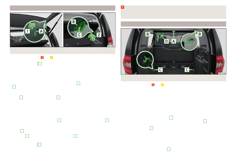
Net partition

Fig. 106  Net partition behind the rear seats

Read and observe   and   on page 86 first.

The net partition can either fitted behind the rear seats or behind the front
seats.

Fitting/removing behind the rear seats

Remove the luggage compartment cover 

» page 89

Luggage compartment

cover.

Remove the net partition from the bag.

Unfold both parts of the cross rod until they are heard to engage.

First insert the rod into the mount 

B


» Fig. 106

 on one side and push it for-

wards. In the same way, insert the cross rod into the mount 

B

 on the other

side of the vehicle.

Hang the carabines 

C

 at the belt ends into the lashing eyes behind the rear

seats.

Pull the belts through the tensioning clasp.

Removingis carried out in the reverse order.

Packing the net partition

Press the red button of the joint 

A


» Fig. 106

. The joint is undone.

89

Transport of cargo

-------------------------------------------------------------------------------------------------------------------------------------------------------------

Put the net partition folded together in the bag and close it.

Attach the bag with the aid of the plastic carabines to the eyes on the left
and right boot trim panel.

Installing and removing the net partition behind the rear seats with variable
loading floor
 is carried out in the same way as behind the rear seats without
variable loading floor. Use the lower fixing eyelets on the carrier rails in order
to attach the carabines.
Installing and removing the net partition behind the front seats is carried out
in the same way as behind the rear seats. Use the fixing eyelets on the rear of
the front seats to attach the carabines. To enlarge the boot, the rear seats can
be removed 

» page 72

.

The opening 

D


» Fig. 106

 in the net partition is for passing the three-point

seat belt 

» page 15

 through.

Storage compartments

Fig. 107  Storage compartment on the left / right

Read and observe   and   on page 86 first.

The cover for the storage compartment 

A


» Fig. 107

 can be removed, thus en-

larging the boot.

Grasp the top part of the cover 

A

 and carefully remove it in the direction of

the arrow.

The storage compartment 

A

is suitable for stowing small objects weighing up

to 1.5 kg in total, and the compartment 

B

 up to 0.5 kg.

Removable storage box

Fig. 108 
Storage box

Read and observe   and   on page 86 first.

The storage box 

» Fig. 108

 is placed under the variable loading floor and can be

taken out.
There is a storage space for the vehicle tool kit under the storage box

» page 155

Vehicle tool kit.

WARNING

The removable storage box must be located under the variable loading
floor for the safe use of the variable loading floor.

Removable lamp

Fig. 109 
Removable lamp

90

Using the system

-------------------------------------------------------------------------------------------------------------------------------------------------------------

Fig. 110  Removable light: Removing / Inserting

Read and observe   and   on page 86 first.

The light is located on the right side of the luggage compartment and is used
to light the luggage compartment or as a portable light.
The lamp is fitted with magnets. As a result, this can, for example, be fitted to
the vehicle body.
Description of the light 

» Fig. 109

Button to turn on / off the light
Part that lights up when the lamp is in the mount
Part that lights up when the lamp is not in the mount

If the light is in the mount, this will illuminate when the boot lid is opened.

To remove, hold the light in the area 

D

 and swivel in the direction of arrow

1

» Fig. 110

.

To switch on the removed light, press button 

A

» Fig. 109

. Pressing the light

again will switched it off.

To insert, first of all insert the light with the rear part 

E

 into the mount

» Fig. 110

 and then push the light in the direction of arrow 

2

 until it audibly

clicks into place.

If the light is not switched off and is correctly inserted in the mount, the LED
diodes in the front part of the light 

C

» Fig. 109

 are automatically switched off.

If the lamp is not correctly inserted into the holder, this does not light up when
the boot lid is opened and the rechargeable batteries are not charged.

A
B
C

Lamp charges
The lamp is supplied by three rechargeable type NiMH AAA batteries. The bat-
teries are charged continuously with the engine running (to fully charge the
battery takes approximately 3 hours).
Replace batteries 

» page 164

.

CAUTION

The light is not waterproof, so it must be protected from humidity - otherwise
there is risk of damage.

Class N1 vehicles

Read and observe   and   on page 86 first.

On class N1 vehicles, which are not fitted with a protective grille, a lashing set
which complies with the standard EN 12195 (1 - 4) must be used for fastening
the load.
Proper functioning of the electrical installation is essential for safe vehicle op-
eration. It is important to ensure that the electrical installation is not damaged
during the adjustment process or when the storage area is being loaded and
unloaded.

Variable loading floor in the luggage compartment (Estate)

Introduction

This chapter contains information on the following subjects:
Removing/fitting variable loading floor

92

Secure the variable loading floor in the raised position

92

Removing/installing the carrier rails

92

Using the variable loading floor with a spare wheel

92

The variable loading floor makes it easier to handle bulky goods and creates an
even surface when the rear seat backrests are folded forward.
The maximum permissible load of the variable loading floor is 75 kg.

91

Transport of cargo

-------------------------------------------------------------------------------------------------------------------------------------------------------------

Removing/fitting variable loading floor

Fig. 111  Fold up / removal variable loading floor

To fold together, grasp the variable loading floor on handle 

A

 and lift in the

direction of arrow 

1

» Fig. 111

.

Fold up the variable loading floor in direction of arrow 

2

.

Pull on both sides of the locking levers in direction of arrow 

3

.

Remove the variable loading floor in direction of arrow 

4

.

Insertion takes place in reverse order.

Secure the variable loading floor in the raised position

Fig. 112 
Secured loading floor in the
raised position

Fold up the hooks on the fastening strip in direction of arrow 

1


» Fig. 103

 on

page 88.

Fold up the variable loading floor behind the rear back backrests.

Fold down the hooks in direction of arrow 

3


» Fig. 103

 on page 88 as far as

the stop.

Support the variable loading floor on the hooks folded downwards 

» Fig. 112

.

Removing/installing the carrier rails

Fig. 113  Slacken check points/remove carrier rails

Removing

Undo the securing points 

B


» Fig. 113

 on the carrier rails using the vehicle

key or a flat screwdriver.

Hold the carrier rail 

A

 in the front area and remove by pulling in the direction

of arrow 

1

.

Hold the carrier rail 

A

 in the rear area and loosen and remove by pulling in

the direction of arrow 

2

.

Fitting

Position the carrier rails on the sides of the boot.

Press the two securing points 

B


» Fig. 113

 on each carrier rail to the stop.

Check the attachment of the carrier rails by pulling it.

Using the variable loading floor with a spare wheel

Fig. 114  Fold up the side panels of the variable loading floor / space under
the variable loading floor

92

Using the system

-------------------------------------------------------------------------------------------------------------------------------------------------------------

The sides of the variable loading floor can be folded in the direction of arrow

» Fig. 114

 - .

The room under the variable loading floor 

» Fig. 114

 -  can be used to stow

the load.

Transportation on the roof rack

Roof load
The maximum permitted weight of the load incl. carriers is 100 kg.

WARNING

The following instructions must be observed to aid road safety when trans-
porting cargo on the roof rack.

Always distribute the load on the roof rack evenly and secure properly

with suitable lashing straps or tensioning straps.

When transporting heavy objects or objects which take up a large area on

the roof rack system, the handling of the car may change as a result of the
displacement of the centre of gravity. The style of driving and speed must
therefore be adapted to the current circumstances.

The permissible roof load, permissible axle loads and permissible total ve-

hicle weight must not be exceeded under any circumstances – risk of acci-
dent!

CAUTION

Make sure that the sliding / tilting roof or the boot lid does not collide with

the roof load when opened.

Ensure the roof aerial is not impaired by the load being transported.

Note

We recommend that you use a roof rack from ŠKODA Original Accessories.

Heating and ventilation

Heating, manual air conditioning system, Climatronic

Introduction

This chapter contains information on the following subjects:
Heating and manual air conditioning

94

Climatronic (automatic air conditioning)

94

Climatronic - automatic operation

95

Air distribution control

96

Air outlet vents

96

The heater heats and ventilates the vehicle interior. The air conditioning sys-
tem also cools and dehumidifies the vehicle interior.
The heating effect is dependent upon the coolant temperature, thus full heat
output only occurs when the engine has reached its operating temperature.
The cooling system works under the following conditions.

The cooling system is switched on.
The engine is running.
The outside temperature is above 2 °C.
The blower is switched on.

When the cooling system is switched on, it prevents misting of the windscreen
and windows.
It is possible to boost the effectiveness of the cooling system by briefly acti-
vating the air recirculation system

» page 96

.

Health protection
To reduce health risks (e.g. common colds), the following instructions for the
use of the cooling system are to be observed.

The difference between the outside temperature and the inside temperature
should not be greater than 5 °C.

The cooling system should be turned off about 10 minutes before the end of
the journey.

Once a year, a disinfection of the air conditioner is to be carried out by a spe-
cialist company.

93

Heating and ventilation

-------------------------------------------------------------------------------------------------------------------------------------------------------------

WARNING

The blower should always be on to prevent the windows from misting.

Otherwise there is a risk of accident.

Under certain circumstances, air at a temperature of about 5 °C can flow

out of the vents when the cooling system is switched on.

Note

The air inlet in front of the windscreen must be free of e.g. ice, snow or

leaves to ensure that the heating and cooling system operates properly.

After switching on the cooling Condensation from the evaporator of the air

conditioning may drip down and form a puddle below the vehicle. This is not a
leak!

If the coolant temperature is too high, the cooling system is switched off to

ensure that the engine cools down.

Heating and manual air conditioning

Fig. 115  Controls of the heating / air conditioning

Read and observe   on page 94 first.

Individual functions can be set or switched on by turning the dial or pressing
the corresponding button 

» Fig. 115

.

Set the temperature

 Reduce the temperature / 

 Increase the temperature

Setting the fan speed (level 0: Fan off, level 4: high-speed)
Set the direction of the air outlet 

» page 96

Switching the cooling system on/off
Switch on/off the rear window heater 

» page 63

A

B
C



Switch the aux. heating and ventilation on/off 

» page 98

Switch recirculation on/off 

» page 96

When the function is switched on, the indicator light in the button lights up.

Information on cooling system
After pressing the button  the indicator light on the button lights up, even if
not all the conditions for the cooling system have been met. The cooling sys-
tem starts to work as soon as the following conditions have been met

» page 93

.

Note

To ensure adequate thermal comfort, during operation of the manual air condi-
tioning there could be an increase in the engine idle speed in some circum-
stances.

Climatronic (automatic air conditioning)

Fig. 116  Controls the Climatronic

Read and observe   on page 94 first.

Individual functions can be set or switched on by turning the dial or pressing
the corresponding button 

» Fig. 116

.

Adjust the temperature for the left side (or for both sides)

 Reduce the temperature / 

 Increase the temperature

Interior temperature sensor
Depending on equipment fitted:

 Switching the windscreen heater on/off 

» page 63

 Switch the aux. heating and ventilation on/off 

» page 98

Adjust the temperature for the right side

 Reduce the temperature / 

 Increase the temperature

A

B
C

D

94

Using the system

-------------------------------------------------------------------------------------------------------------------------------------------------------------

Adjust the blower speed

 Increase speed

 Decrease speed

Switching the airflow to the windscreen on and off

Air flow to the windows
Air flow to the upper body
Air flow in the footwell

Switch the automatic recirculation on/off 

» page 96

Switch on/off the rear window heater 

» page 63

Switching automatic mode on 

» page 95

Switch the Climatronic system off
Switching the cooling system on/off

Switch the temperature setting in Dual mode on/off

When the function is switched on, the indicator light in the button lights up.

After the cooling system is switched off, only the ventilation function remains
active whereby the minimum temperature that can be reached is the outside
temperature.

Setting temperature
The interior temperature for the left and right side can be set separately or to-
gether.
The temperature for both sides, is set by turning the knob 

A


» Fig. 116

 (the

indicator light in the button  is not illuminated).
The temperature for the right side is adjusted by turning the knob 

D

 (the in-

dicator light in the button  is lit).
The temperature for the left side is adjusted by turning the knob 

A

 (the indi-

cator light in the button  is lit).
At a temperature setting below 18 ° C at the start of the numerical scale, the
symbol 

 will illuminate, Climatronic is using Maximum cooling performance.

At a temperature setting above 26 ° C at the end of the numerical scale, the
symbol

 will illuminate, Climatronic is using maximum heat output.

There is no automatic temperature control in the two end positions. In the
range between 18 °C to 26 °C, an automatic temperature control takes place.









Controlling blower
The Climatronic system controls the blower stages automatically in line with
the interior temperature. However, the blower stages can be manually adap-
ted to suit your particular needs.
If the blower speed is reduced to a minimum, Climatronic is switched off.
The set blower speed is displayed above the buttonwhen the respective
number of indicator lights come on.

CAUTION

Do not cover the interior temperature sensor 

H


» Fig. 116

 - the function of the

Climatronic could be impaired.

Note

If the windscreen mists up, press the button. Press the button  once

the windscreen has demisted.

In order to ensure adequate thermal comfort, there may be an increase in en-

gine idle speed during operation of the Climatronic in some circumstances.

Climatronic - automatic operation

Read and observe   on page 94 first.

The automatic mode is used in order to maintain a constant temperature and
to demist the windows in the interior of the car.
If the warning light in the top right corner of the button  lights up, the Cli-
matronic operates in “HIGH”-mode.
Upon pressing the  button again, the Climatronic switches to “LOW”-mode
and the indicator light in the top left corner lights up. The Climatronic uses on-
ly in this mode the lower blower speed. However taking into account the noise
level, this is more comfortable, yet be aware that the effectiveness of the air
conditioning system is reduced particularly if the vehicle is fully occupied.
By pressing the button  again, it is changed to “HIGH”-mode.
Automatic mode can be switched off by pressing one of the buttons for the air
distribution or by increasing/decreasing the blower speed. The temperature
regulation is continued.

Note

Climatronic is set to the “HIGH” mode at the factory.

95

Heating and ventilation

-------------------------------------------------------------------------------------------------------------------------------------------------------------

Air distribution control

Read and observe   on page 94 first.

The recirculation mode prevents contaminated outside air getting into the in-
terior of the vehicle. In recirculated air mode air is sucked out of the interior of
the vehicle and then fed back into the interior.

Heating and manual air conditioning system

To switch on press thebutton.

To switch off, press the  button again.

If the air distribution control is set to position  when the recirculation modes
is switched on, the recirculated-air mode is switched off.
By pressing the  button, the air recirculation also in this position can be
switched on again.

Climatronic (automatic air conditioning)

To turn the recirculation mode on, press the Symbol key  repeatedly until
the indicator light is lit on the left side of the button.

To activate the automatic recirculation mode, press the Symbol key  re-
peatedly until the indicator light is lit on the right side of the button.

The Climatronic can have a sensor that measures the air recirculation mode
and automatically turns on if there is an increased concentration of pollutants
in the incoming air.
When the pollutant concentration decreases to the normal level, the recircula-
ted air mode is automatically switched off.
If the air quality sensor does not automatically switch on the recirculated air
mode, you can switch it on yourself by pressing the button . The indicator
light lights up in the button on the left side.
To turn off the air recirculation or to deactivate the automatic air recircula-
tion
, press the  button of press the  symbol button repeatedly until the
warning lights in the button go out.

WARNING

The recirculation system cannot be switched on for a longer period of time,
because no fresh air is fed through from the outside. “Stale air” may result
in fatigue in the driver and occupants, reduce attention levels and also
cause the windows to mist up. As soon as windows mist up, turn on the re-
circulation system immediately - There is a risk of accident!

CAUTION

We recommend not smoking in the vehicle when the recirculating air operation
is switched on. The smoke sucked from the interior is deposited on the evapo-
rator of the air conditioner. This produces a permanent odour when the air
conditioning system is operating which can only be eliminated through consid-
erable effort and expense (replacement of compressor).

Note

The Climatronic automatic air distribution control operates only if the outside
temperature is higher than approx. 2 °C.

Air outlet vents

Fig. 117  Air vents at the front

96

Using the system

-------------------------------------------------------------------------------------------------------------------------------------------------------------

Fig. 118  Air vents at the rear

Read and observe   on page 94 first.

The direction of airflow can be adjusted using the air outlet vents 34 

» Fig. 117

and 6 

» Fig. 118

 – the outlets can be opened and closed individually.

Setting the airflow direction from the air outlet nozzles 3 and 4 takes place by
moving the adjusting units

A


» Fig. 117

 in the desired direction.

Setting the airflow direction from the air outlet nozzles 6 takes place by turn-
ing the controller 

C

 or. 

D


» Fig. 118

 in the desired direction.

To open / close the air outlet nozzles 3 and 4 the Turn the controller 

B

 into

position / 0 

» Fig. 117

.

To open / close the air outlet nozzles 6

C

 turn the controller between the

end positions / in the final position 

» Fig. 118

.

Depending on the setting for air distribution, the air will flow from the follow-
ing air vents.

Set the direction of the air

outlet

Air vents 

» Fig. 117

 and 

» Fig. 118



124

12457

346

457

CAUTION

Do not cover the air vents - the air distribution could be compromised.

Note

The air outlet vents 6 

» Fig. 118

 are only fitted on vehicles with the higher cen-

tre console.

Auxiliary heating (auxiliary heating and ventilation)

Introduction

This chapter contains information on the following subjects:
Switch on / off

98

System settings

98

Remote control

99

The aux. heating heats the vehicle interior as well as the engine. For heating,
fuel is consumed from the fuel tank.
The auxiliary ventilation enables fresh air to flow into the vehicle interior with
the engine switched off, whereby the interior temperature is effectively de-
creased (e.g. with the vehicle parked in the sun).
The aux. heating (aux. heating and ventilation) (referred to just as aux. heating
in the following) ensures the heating / ventilation depending on the setting of
the air conditioning and the air outlet vents before switching off the ignition.

WARNING

The auxiliary heating must never be operated in closed rooms (e.g. garag-

es) – There is a risk of poisoning!

The auxiliary heating must not be allowed to run during refuelling – risk

of fire.

The exhaust pipe of the auxiliary heating is located on the underside of

the vehicle. If you want to use the auxiliary heating, do not park the car in
places where the exhaust fumes can come into contact with flammable
materials such as dry grass, undergrowth, leaves, spilled fuel etc. - risk of
fire.

CAUTION

The air inlet in front of the windscreen must be free (e.g. of ice, snow or
leaves) to ensure that the auxiliary heating operates properly.

97

Heating and ventilation

-------------------------------------------------------------------------------------------------------------------------------------------------------------

Note

The aux. heating only switches the blower on, if it has achieved a coolant

temperature of approx. 50 °C.

In the engine compartment, water vapour may form during the operation of

the aux. heating.

Switch on / off

Fig. 119  Button for directly switching the operating part of the manual air
conditioning/Climatronic on/off

Read and observe   and   on page 97 first.

Functional requirements of the aux. heating.

The charge state of the vehicle battery is sufficient.
The fuel supply is adequate (the warning light 

 is not illuminated in the

instrument cluster).

Direct switching on/off
The aux. heating can be directly switched on or off at any time using the but-
ton 

» Fig. 119

 on the operating part of the air-conditioning system, or the Cli-

matronic or via the radio remote control 

» page 99

.

Automatic on / off

Over a set and activated preset time in the MAXI DOTDisplay.

According to the environmental conditions.

If the auxiliary heating has not already been switched off, it switches off auto-
matically after the running time set in the Running time menu.
Switching off the auxiliary heating takes place automatically when there is a
lack of fuel (warning light 

 in the instrument cluster lights up).

After switching off the system, the coolant pump and the aux. heating will
continue running a little while longer in order to burn the remaining fuel in the
heating.
For vehicles with gasoline engines, the automatic switching on and off of the
heater can be disabled in a specialist workshop.

System settings

Read and observe   and   on page 97 first.

The following menu items can be selected from the Aux. heating menu item in
the MAXI DOT display (depending on the vehicle equipment).

Day of the wk. - set the current day of the week

Running time - Set the required running time in 5 minute increments. The run-
ning time can be 10 to 60 minutes.

Mode - Set the desired heating/ventilation mode

Starting time 1Starting time 2Starting time 3 - for each pre-set time, the day and
the time (hour and minute) can be set for switching on the auxiliary heating.
An empty position can be found between Sunday and Monday when select-
ing the day. If this empty position is selected, the activation is performed
without taking into account the day.

Activate - Activate pre-set mode

Deactivate - Deactivate pre-set mode

Factory setting. - Restore factory setting

Back - return to main menu.

Only one programmed pre-set time can be active.
The last programmed pre-set time remains active.
After the auxiliary heating activates at the set time, it is necessary to pre-set a
time again.
If the pre-set menu is closed by selecting the Back menu item or if no changes
are made on the display for more than 10 seconds, the set values are stored,
but the pre-set time is not activated.
An indicator light on the button is illuminated when the system is running.
The system in operation switches off on expiration of the operating duration
or can be deactivated earlier by pressing the direct on/off buttonor by using
the radio remote control.

98

Using the system

-------------------------------------------------------------------------------------------------------------------------------------------------------------

Remote control

Fig. 120 
Radio remote control

Read and observe   and   on page 97 first.

Description of the remote control 

» Fig. 120

Aerial
Warning light
Switch on the auxiliary heating
Switch off the auxiliary heating

To switch the remote control on or off, hold the remote control vertically, with
the aerial 

B


» Fig. 120

 pointing upwards. The antenna must not be covered

with the fingers or the palm of the hand during this process.
The auxiliary heating can only be switched on/off safely using the remote con-
trol if the distance between the radio remote control and the vehicle is at least
2 m.

Display warning light 

B

Meaning

Lights up green for 2 seconds.

The auxiliary heating has been
switched on.

Lights up red for 2 seconds.

The auxiliary heating has been
switched off.

Slowly flashes green for 2 seconds.

The ignition signal was not received.

Quickly flashes green for 2 seconds.

The aux. heating is blocked, e.g. be-
cause the tank is nearly empty or
there is a fault in the aux. heating.

Flashes red for 2 seconds.

The switch off signal was not re-
ceived.

A
B





Display warning light 

B

Meaning

Lights up orange for 2 seconds, then
green or red.

The battery is weak, however the
switching on or off signal was re-
ceived.

Lights up orange for 2 seconds, then
flashes green or red.

The battery is weak, however the
switching on or off signal was not re-
ceived.

Flashes orange for 5 seconds.

The battery is discharged, however
the switching on or off signal was not
received.

Replace the battery 

» page 164

.

CAUTION

The remote control must be protected against moisture, severe shocks and

direct sunlight - there is a risk of damage to the remote control.

The range of the remote control with a charged battery is a few hundred me-

tres (depending on obstructions between the remote control and the vehicle,
weather conditions, the battery condition etc.).

99

Heating and ventilation

-------------------------------------------------------------------------------------------------------------------------------------------------------------

Driving

Starting-off and Driving

Starting and stopping the engine

Introduction

This chapter contains information on the following subjects:
Electronic immobiliser and steering lock

100

Switch on/off ignition

101

Starting / stopping the engine

101

Problems with the engine start - vehicles with starter button

102

Depending on equipment fitted, it is possible to switch the ignition on/off and
start/stop the engine with the key in the ignition or using the starter button.

WARNING

Never switch off the engine before the vehicle is stationary – There is a

risk of accident!

While driving with the engine stopped the ignition must always be

switched on. Otherwise, the steering may lock - There is a risk of an acci-
dent!

Do not withdraw the ignition key from the ignition lock until the vehicle

has come to a stop 

» page 105

Parking. Otherwise, the steering may lock -

danger of an accident!

Never leave the vehicle unattended with the engine running - there is a

risk of theft etc!

Never (e.g. in garages) run the engine in a closed place - there is a risk of

poisoning and death!

CAUTION

Only start the engine when the engine and the vehicle are stationary - there

is a risk of starter and engine damage!

Do not push-start the engine – There is a risk of damaging the engine and

the catalytic converter! The battery from another vehicle can be used as a
jump-start aid.

On vehicles with the starter button, pay attention to where the key is loca-

ted. The system can recognize the valid key, even if it has been accidentally
left on the vehicle roof - there is danger of loss or damage to the key!

Note

Do not warm up the engine while the vehicle is stationary. If possible, start
your journey as soon as the engine has started. Through this, the engine rea-
ches its operating temperature faster.

Electronic immobiliser and steering lock

Read and observe   and   on page 100 first.

The electronic immobilizer (hereafter referred to as immobilizer) makes the
theft or unauthorised use of your vehicle more difficult.

Immobilizer
The immobilizer allows the engine to start provided an original vehicle key only
is used.

Malfunction of the immobilizer
If a component in the immobiliser key fails, it is not possible to start the en-
gine. A corresponding message appears in the display of the instrument clus-
ter to explain the immobiliser is active.
To start, use the other vehicle key or seek help from a specialist garage.

Steering lock - lock

On vehicles with ignition lock, remove the key and turn the steering wheel
until the steering lock engages.

On vehicles with a starter button, switch off the ignition and open the driv-
er's door. If the driver's door is opened and the ignition is switched off after-
wards, the steering is only locked automatically after the vehicle has been
locked.

Steering lock - unlock

On vehicles with ignition lock, insert the key into the ignition and turn on the
ignition. If this is not possible, then move the steering wheel slightly back
and forth, as a result of which the steering lock should unlock.

On vehicles with starter button, get into the car and close the driver's door.
Under certain circumstances, the steering lock can be unlocked only when
the ignition is switched on or the engine is started.

WARNING

Never let the vehicle roll with locked steering lock - there is a risk of acci-
dent!

100

Driving

-------------------------------------------------------------------------------------------------------------------------------------------------------------

Switch on/off ignition

Fig. 121  Positions of the vehicle key in the ignition lock / starter button

Read and observe   and   on page 100 first.

Positions of the vehicle key in the ignition lock 

» Fig. 121

 - 

Ignition switched off, engine switched off
Ignition switched on
Starting engine

Switching on /off ignition in vehicles with starter button

Press the 

» Fig. 121

 -  button, the ignition is turned on / off.

On vehicles with manual transmission, the pedal must not be depressed to
switch on / off the ignition, otherwise the engine will start.
On vehicles with automatic transmission, the brake pedal must not be de-
pressed to switch on / off the ignition, otherwise the engine will start.

Starting / stopping the engine

Read and observe   and   on page 100 first.

Before starting the engine

Firmly apply the handbrake.

For vehicles with manual transmission, shift gear stick to neutral, depress
the clutch pedal and hold it there until the engine starts.

For vehicles with automatic transmission, place the selector lever in position
P or N and 

» 

depress the brake pedal until the engine starts.

1

2
3

Starting engine

On vehicles with ignition lock, turn the key to position 

3

 and the engine

starts

» Fig. 121

 on page 101 . Then release the key, the engine will start au-

tomatically.

If the engine does not start within 10 seconds, turn the key to position 

1

. Re-

peat the start-up process after 30 s.

On vehicles with starter button, press the button briefly 

» Fig. 121

 on

page 101 - , the motor will start automatically.

On vehicles with diesel engines the glow plug warning light 

 goes on during

starting. The engine can be started after the indicator light goes out.

Switching off the engine

Stop the vehicle.

On vehicles with ignition lock, turn the key to position 

1


» Fig. 121

 on

page 101 .

On vehicles with starter button, press the button 

» Fig. 121

 on page 101 - ,

the engine and the ignition will be switched off simultaneously.

For vehicles with automatic transmission, the ignition key can only be removed
if the selector lever is in position P.
Do not switch the engine off immediately at the end of your journey if the en-
gine has been working at high revs over a prolonged period, but leave it to run
at an idling speed for about 1 minute. This prevents any possible accumulation
of heat when the engine is switched off.

Emergency shutdown of the engine in vehicles with starter button
The system is equipped with a protective device against accidental switching
off, the engine can only be shut off while driving in the event of an emergency.

Keep the knob pressed 

» Fig. 121

 on page 101 -  or press it twice within 1

second.

After the emergency stop of the engine, the steering lock will remain un-
locked.

CAUTION

When the outdoor temperature is below -10 ° C, the selector lever when start-
ing must always be in P mode.

101

Starting-off and Driving

-------------------------------------------------------------------------------------------------------------------------------------------------------------

Note

The engine running noises may be louder at first for a short time after start-

ing the cold engine.

You should not switch on any major electrical components during the heat-

ing period, otherwise the vehicle battery will be drained unnecessarily.

After switching off the ignition, the radiator fan may (also intermittently)

continue to operate for approx. 10 minutes.

Problems with the engine start - vehicles with starter button

Fig. 122 
Starting the engine - Press the
button with the key

Read and observe   and   on page 100 first.

If no engine start is possible and the display of the instrument cluster shows a
message that the key could not be detected by the system or there is a system
fault, then try to start the engine as follows.

Press the starter button with the key 

» Fig. 122

.

If the engine does not start, the help of a specialist garage is required.

CAUTION

The key may not be detected by the system if the battery in the key is running
out of charge or the signal fails (strong electromagnetic field) or is shielded
(e.g. in an aluminium case).

START-STOPsystem

Introduction

This chapter contains information on the following subjects:
Operation

102

Manually deactivating/activating the system

103

The START STOPsystem (hereinafter referred to as the system) reduces
CO

2

emissions and harmful emissions, and saves fuel.

If the system determine that the engine is not needed when the vehicle stops
(e.g. at the traffic lights), it turns off the engine and starts it again when mov-
ing off.
The system function depends on many factors. Some of them are down to the
driver, the others are systemic and can neither be influenced nor identified.
Therefore the system may react differently in situations which seem identi-
cal from the driver's perspective.
The system is automatically activated every time the ignition is switched on
(even where this has previously been manually deactivated with the button ).

Note

If the engine has stopped due to the system, the ignition remains on.

Operation

Fig. 123 
Prompt in the MAXI DOT display

Vehicles with manual transmission
The engine is automatically switched off as soon as the vehicle comes to a
halt, the shift lever is moved into neutral and the clutch pedal is released.
The engine is automatically started as soon as the clutch pedal is depressed.

Vehicles with automatic transmission
The engine is automatically switched off as soon as the vehicle comes to a halt
and the brake pedal is operated.
The engine is automatically started as soon as the brake pedal is released.

102

Driving

-------------------------------------------------------------------------------------------------------------------------------------------------------------

Requirements for the system to function correctly
The following conditions must be met for the system to function correctly.

The driver's door is closed.
The driver has fastened the seat belt.
The driving speed was higher than 4 km.h after the last stop.
No trailer or other accessory is connected to the trailer socket.

System status
The system status is indicated in the instrument cluster display when stopped.
The engine is automatically switched off; when the vehicle moves off the igni-
tion process will be automatically initiated.


» Fig. 123

START-STOP ACTIVE

The engine is not automatically switched off.


» Fig. 123

START-STOP NOT POSSIBLE

The engine does not shut down when the vehicle stops, if e.g. the following
applies.

The engine temperature for the proper function of the system has not yet
been reached.

The charge state of the vehicle battery is too low.

The current consumption is too high.

High air conditioning or heating output (high fan speed, big difference be-
tween the desired and actual interior temperature).

If the engine has shut down automatically but the system detects that the en-
gine is required to run (e.g. if the brake pedal is pressed repeatedly) then the
system automatically starts up the engine.
If there is a system fault, the following message will appear in the display of
the instrument cluster. Seek help from a specialist garage.

Note

If the driver's seat belt is removed for more than 30 seconds or the driver's

door is opened after the engine has switched off automatically, the engine will
have to be restarted manually.

No automatic engine shut-down takes place when a vehicle with automatic

transmission is moving at low speed (e.g. during a traffic jam) and remains sta-
tionary after pressing the brake pedal lightly. Automatic engine shutdown
takes place if you press the brake pedal down with more force.

For vehicles with automatic transmission there is no automatic engine shut-

down when the system detects a manoeuvring action due to a large steering
angle.

Manually deactivating/activating the system

Fig. 124 
Button for the START-STOP sys-
tem

To deactivate/activate the system, press the  button

» Fig. 124

.

When the system is deactivated, the symbol 

in the button lights up.

If the system is turned off, it will be automatically reactivated after turning the
ignition off and on.

Note

If the system is deactivated when the engine is turned off automatically, then
the automatic start process takes place.

Brakes and parking

Introduction

This chapter contains information on the following subjects:
Handbrake

104

Parking

105

103

Starting-off and Driving

-------------------------------------------------------------------------------------------------------------------------------------------------------------

The wear and tear on the brake pads is dependent on the operating condi-
tions and driving style. In difficult conditions (e.g. urban, sporty driving), the
condition of the brakes should be checked between services by a specialist ga-
rage.
Brake response can be slower if the brakes are covered in moisture or, in win-
ter, have a layer of ice or salt on them
. The brakes should be cleaned and
dried by applying the brakes many times over 

» 

.

Corrosion on the brake discs and dirt on the brake pads can occur if the vehicle
has been parked for a long period and if you do not make much use of the
braking system. The brakes are cleaned by applying the brakes several times
over 

» 

.

Before negotiating a long or steep gradient, reduce speed and shift down a
gear. As a result, the braking effect of the engine will be used, reducing the
load on the brakes. If, nevertheless, there is a need for additional braking, it
should be carried out at intervals.
Emergency braking warning - if it is necessary to brake hard, the system may
cause the brake lights to automatically flash, to alert the traffic behind.
New brake pads must first be “run in” because these do not initially have the
best possible braking effect. Drive especially carefully for the first 200 km or
so.
If the brake fluid level is too low, it can cause faults in the braking system;
the warning light 

 will light up in the instrument cluster 

» page 32

Braking

system. If the warning light does not light up, yet the stopping distance is per-
ceived to be longer than before, the driving style should be adapted in view of
the unknown cause of the problem, and braking kept to a minimum - seek the
help of a specialist garage without delay.
The brake booster increases the pressure generated with the brake pedal. The
brake booster only operates when the engine is running.

WARNING

Greater physical effort is required for braking when the engine is switch-

ed off – risk of accident!

During the braking procedure on a vehicle with manual transmission,

when the vehicle is in gear and at low revs, press the clutch pedal. Other-
wise, the functionality of the brake system may be impaired – risk of acci-
dent!

WARNING (Continued)

Do not depress the brake pedal if there is no requirement to slow down.

This causes the brakes to overheat and can also result in a longer braking
distance and excessive wear - There is a risk of an accident!

Only brake for the purpose of drying and cleaning the brake discs if the

traffic conditions permit this. Do not place any other road users in jeopardy.

Recommendations for new brake pads should be followed.

When stopping and parking, the parking brake should always be applied

firmly, otherwise the vehicle could move off - There is risk of an accident!

If a front spoiler, full wheel trim, etc. is mounted retrospectively, it must

be ensured that the air supply to the front wheel brakes is not reduced.
Otherwise, the front brakes could be in danger of overheating – There is
risk of an accident!

Handbrake

Fig. 125 
Handbrake

Read and observe   on page 104 first.

The handbrake secures the vehicle against unwanted movement when stop-
ping and parking.

Apply

Pull the handbrake lever firmly upwards.

Release

Pull the handbrake lever up slightly and at the same time push in the lock
button 

» Fig. 125

 .

Move the lever right down while pressing the lock button.

The handbrake warning light 

 lights up when the handbrake is applied, pro-

vided the ignition is on.

104

Driving

-------------------------------------------------------------------------------------------------------------------------------------------------------------


Content      ..     4      5      6      7     ..