Renault Master (2018 year). Instruction - part 16


  Index      Renault     Renault Master - instruction 2018 year in english


Search            


Content   ..  14  15  16  17   ..


Renault Master (2018 year). Instruction - part 16


5.34

BATTERY: troubleshooting 

(2/2)

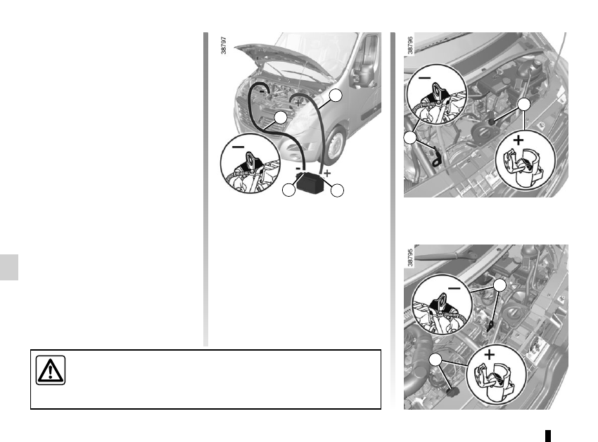
Attach the positive lead (+) A to termi-

nal 3, then to terminal 2 (+) of the bat-

tery supplying the current.
Attach negative lead (–) B to terminal 1 

(–) of the battery supplying the current, 

then to earth 4 (–).
Start the engine as normal. As soon as 

it is running, disconnect leads A and B 

in the reverse order (4-3-2-1).

Starting the vehicle using the 

battery from another vehicle

If you have to use the battery from an-

other vehicle to start, obtain suitable 

jump leads (with a large cross section) 

from an approved dealer or, if you al-

ready have jump leads, ensure that 

they are in perfect condition.
The two batteries must have an iden-

tical nominal voltage of 12 volts. The 

battery supplying the current should 

have a capacity (amp-hours, Ah) which 

is at least the same as that of the dis-

charged battery.
Ensure that there is no risk of contact 

between the two vehicles (risk of short 

circuiting when the positive terminals 

are connected). Switch off your vehicle 

ignition.
Start the engine of the vehicle supply-

ing the current and run it at a moderate 

speed.

A

B

2

1

Check that there is no contact between leads A and B and that the posi-

tive lead A is not touching any metal parts on the vehicle supplying the 

current.
Risk of injury and/or damage to the vehicle.

3

4

4

3

5.35

RADIO FREQUENCY REMOTE CONTROL: battery

Replacing the battery

Open the case at slot 1 using a flat-

blade screwdriver or similar and re-

place the battery 2, observing the type 

and polarity shown on the back of the 

cover.

Note:  It is not advisable to touch the 

electrical circuit in the key cover when 

replacing the battery.

3

When refitting, ensure that the cover 

is correctly clipped on and the screw 

tightened.

1

2

3

2

A

1

Special feature of key A

Undo screw 3 to remove the remote 

control cover.

Do not dispose of your used batter-

ies in the countryside. Give them to 

an organisation that collects and re-

cycles used batteries.

The batteries are available from ap-

proved Dealers, and their service 

life approximately two years. Check 

that there is no dye on the battery: 

risk of an incorrect electrical con-

tact.

5.36

HANDS-FREE ACCESS TRANSMITTER, RECEIVER: battery

Replacing the battery

Use a coin to open the unit via slot 1.

Do not dispose of your used 

batteries in the countryside. 

Give them to an organisa-

tion that collects and recy-

cles used batteries.

1

2

Replace battery 2 according to the di-

rection marked on the cover.
Note:  it is not advisable to touch the 

electronic circuit in the cover when re-

placing the battery.

When refitting, ensure that the cover 

is correctly clipped into place.

The batteries are available from ap-

proved Dealers, and their service 

life approximately two years.
Check that there is no dye on the 

battery: risk of an incorrect electri-

cal contact.

5.37

WIPER BLADES

– press tab 3 and slide the wiper blade 

downwards to release hook 5 from 

the wiper arm;

–  slide the blade (A) then lift it (B) to 

release it.

Refitting
To refit the wiper blade, proceed in the 

reverse order to removal. Make sure 

that the blade is correctly locked in po-

sition.

Check the condition of the wiper 

blades. You are responsible for their 

service life:
–  clean the blades and the wind-

screen regularly with soapy 

water;

–  do not use them when the wind-

screen is dry;

–  free them from the windscreen 

when they have not been used 

for a long time.

– In frosty weather, make 

sure that the wiper blades 

are not stuck by ice (to 

avoid the risk of the motor 

overheating).

–  

Check the condition of the wiper 

blades.

Replace the wiper blades as soon 

as they begin to lose efficiency 

(approximately once a year).

Whilst changing the blade, take care 

not to drop the arm onto the window 

after it has been removed as this 

may break the window.

2

3
4

5

B

A

To access the wiper blades, stand on 

step 1.
Note: the step may be slippery.

Replacing windscreen wiper 

blades 2

–  Lift wiper arm 4;
–  move the blade into a horizontal po-

sition;

1

5.38

TOWING: breakdown 

(1/2)

The steering wheel must be un-

locked and the ignition key must be 

in position M (ignition on) to provide 

brake lights and hazard warning 

lights on the towed vehicle. At night 

the vehicle must have its lights on.
Unhitch the trailer, etc., if one is 

being towed.
You must observe the towing regu-

lations which apply in the country in 

which you are driving: do not exceed 

the towing weight for your vehicle.
Contact an approved dealer.

– Use a rigid towing bar. 

If a rope or cable is used 

(where the law allows this), 

the vehicle being towed 

must be able to brake.

–  A vehicle must not be towed if it is 

not fit to be driven.

– Avoid accelerating or braking 

suddenly when towing, as this 

may result in damage being 

caused to the vehicle.

–  When towing a vehicle, it is ad-

visable not to exceed 15 mph 

(25 km/h).

When the engine is 

stopped, steering and brak-

ing assistance are not op-

erational.

Do not remove the key from 

the ignition when the vehi-

cle is being towed.

Towing a vehicle with a 

sequential gearbox

If the gearbox is stuck in a gear:
–  switch on the ignition;
–  select neutral with the brake pedal 

depressed;

–  check that the gearbox is in neutral 

(by pushing the vehicle for example).

If you cannot find neutral you must tow 

the vehicle with the front wheels raised.
The vehicle should always be towed 

with the ignition switched off.

5.39

First screw in towing hitch 4 as far 

as it will go by hand, then finish tight-

ening it fully using the wheelbrace 

stored in tool kit 3.

TOWING: breakdown 

(2/2)

When storing the tools, 

ensure that they are cor-

rectly replaced in unit 3, in 

their original positions and 

store the unit under the driver’s 

seat. Do not leave the tools unse-

cured inside the vehicle as they may 

come loose under braking.

Front towing point 2

Accessing towing hitch 4
Move the driver’s seat forward and re-

cline the seatback so that tool kit 3 can 

be removed.

Access to front towing point 2
Unclip cover 5 by inserting a flat-blade 

screwdriver or similar under the cover.

3

2

5

4

1

Only use:

–  At the rear left, towing point 1.
–  At the front, towing hitch
 4 (from 

the tool kit) and towing point 2.

These towing points may only be used 

for pulling the vehicle, never for lifting it 

either directly or indirectly.

Rear towing point 1

5.40

FITTING THE RADIO

If your vehicle is not fitted with an audio 

system, one can be fitted and locations 

have been provided for:
– radio 1;

– front speakers 2 (depending on the 

vehicle).

To install any equipment, please con-

sult an approved dealer.

Radio location 1

Unclip the blanking cover. The aerial, + 

and – supply and speaker wire connec-

tions are located behind it.

–  In all cases, it is very important to follow the manufacturer’s instructions care-

fully.

–  The specifications of the brackets and wires (available from our network) vary 

depending on the equipment level of your vehicle and the type of radio.

  Consult an approved Dealer to find out the correct part number.
–  No work may be carried out on the vehicle’s electrical or radio circuits, except 

by approved dealers: an incorrectly connected system may result in damage 

being caused to the electrical equipment and/or the components connected to 

it.

1

2

5.41

ACCESSORIES

Electrical and electronic accessories

Before installing this type of accessory (particularly for transmitters/receivers: frequency bandwidth, power level, po-

sition of the aerial, etc.), make sure it is compatible with your vehicle. You can get advice from an authorised dealer.

Connect accessories with a maximum power of 120 Watts only. Fire hazard. When several accessory sockets are 

used at the same time, the total power of the connected accessories must not exceed 180 watts.

No work may be carried out on the vehicle’s electrical or radio circuits, except by authorised dealers: an incorrectly connected 

system may result in damage being caused to the electrical equipment and/or the components connected to it.

If the vehicle is fitted with any aftermarket electrical equipment, make sure that the installation is correctly protected by a fuse. 

Establish the rating and position of this fuse.

Using the diagnostic socket

The use of electronic accessories on the diagnostic socket may cause serious disturbance to the vehicle’s electronic systems. 

For your safety we recommend that you use only electronic accessories approved by the manufacturer, consult an Approved 

Dealer. Serious accident risk.

Use of transmitting/receiving devices (telephones, CB equipment etc.).

Telephones and CB equipment with integrated aerials may cause interference to the electronic systems originally fitted to the 

vehicle: it is advisable only to use equipment with an external aerial. Furthermore, we remind you of the need to conform 

to the legislation in force concerning the use of such equipment.

Fitting aftermarket accessories

If you wish to install accessories on the vehicle: please contact an authorised dealer. Also, to ensure the correct operation of 

your vehicle, and to avoid any risk to your safety, we recommend that you use only accessories specifically designed for your 

vehicle, which are the only accessories for which the manufacturer will provide a warranty.

If you are using an anti-theft device, only attach it to the brake pedal.

Obstructions to the driver

On the driver’s side, only use mats suitable for the vehicle, attached with the pre-fitted components, and check the fitting regu-

larly. Do not lay one mat on top of another. There is a risk of wedging the pedals.

5.42

The starter is activated

POSSIBLE CAUSES

WHAT TO DO

Warning lights dim or fail to come on; 

the starter does not run.

Battery terminals disconnected, 

oxidised or incorrectly secured.

Contact an approved Dealer.

Battery discharged or worn.

Connect another battery to the faulty bat-

tery. Refer to the paragraph “Battery: trou-

bleshooting” in Section 5 or replace the bat-

tery if necessary.

Do not push the vehicle if the steering 

column is locked.

The engine will not start.

Starting conditions are not fulfilled.

Refer to the information on “Starting/stop-

ping the engine” in Section 2.

The steering column remains locked.

Steering wheel locked.

To  unlock, move the key and the steer-

ing wheel (refer to the information on the 

“Ignition switch” in Section 2).

OPERATING FAULTS 

(1/5)

The following advice will enable you to carry out quick, temporary repairs. For safety reasons you should always contact 

an approved dealer as soon as possible.

5.43

On the road

POSSIBLE CAUSES

WHAT TO DO

Vibrations.

Tyres not inflated to the correct pres-

sure, incorrectly balanced or dam-

aged.

Check the tyre pressures: if this is not the 

problem, have them checked by an ap-

proved dealer.

Coolant boiling in the coolant reservoir.

Mechanical fault: damaged cylinder 

head gasket.

Stop the engine.

Contact an approved Dealer.

Smoke under the bonnet.

Short circuit or cooling system leak.

Stop, switch off the ignition, stand away 

from the vehicle and contact an approved 

dealer.

The oil pressure warning light comes 

on:

while cornering or braking

The level is too low.

Top up the engine oil (refer to the informa-

tion on “Engine oil level – Topping up/refill-

ing” in Section 4).

is slow to go out or remains lit under 

acceleration

Loss of oil pressure.

Stop the vehicle and contact an approved 

Dealer.

White smoke from the exhaust.

This is not necessarily a fault. Smoke 

may be caused by regeneration of 

the particle filter.

Refer to the information on “Special fea-

tures of diesel versions” in Section 2.

OPERATING FAULTS 

(2/5)

5.44

On the road

POSSIBLE CAUSES

WHAT TO DO

Steering becomes heavy.

Assistance overheating.
Fault with the electric assistance 

motor.
Fault in the assistance system.

Drive carefully at reduced speed, be aware 

of the level of force in the steering wheel 

needed to turn the wheels. Consult an ap-

proved dealer

The engine is overheating. The cool-

ant temperature warning light and the 

STOP warning light come on.

Engine cooling fan not working.

Stop the vehicle, switch off the engine and 

contact an approved Dealer.

Coolant leaks.

Check the coolant reservoir: it should con-

tain fluid. If there is no coolant, consult an 

approved Dealer as soon as possible.

OPERATING FAULTS 

(3/5)

Radiator: If there is a significant lack of coolant, remember that it must 

never be topped up using cold coolant while the engine is very warm. 

After any procedure on the vehicle which has involved even partial drain-

ing of the cooling system, it must be refilled with a new mixture prepared 

in the correct proportions. Reminder: only products approved by our Technical 

Department may be used for this purpose.

5.45

OPERATING FAULTS 

(4/5)

Electrical equipment

POSSIBLE CAUSES

WHAT TO DO

The wipers do not work.

Wiper blades stuck.

Free the blades before using the wipers.

Faulty electrical circuit.

Consult an approved dealer.

Fuse damaged.

Replace the fuse or have it replaced; refer 

to the information on “Fuses” in section 5.

The wiper does not stop.

Faulty electrical controls.

Consult an approved dealer.

Direction indicators flashing more 

quickly.

Blown bulb.

See the information on “Headlights: chang-

ing bulbs” or “Rear lights: changing bulbs” 

in Section 5.

Fuse damaged.

Replace the fuse or have it replaced; refer 

to the information on “Fuses” in section 5.

The direction indicators do not work.

Faulty electrical circuit.

Consult an approved dealer.

Fuse damaged.

Replace the fuse or have it replaced; refer 

to the information on “Fuses” in section 5.

5.46

Electrical equipment

POSSIBLE CAUSES

WHAT TO DO

The lights do not come on or go off.

Faulty electrical circuit or control.

Consult an approved dealer.

Fuse damaged.

Replace the fuse or have it replaced; refer 

to the information on “Fuses” in section 5.

Traces of condensation in the head-

lights or rear lights.

Traces of condensation may be a nat-

ural phenomenon caused by varia-

tions in temperature and humidity.
In this situation, these traces soon dis-

appear when the lights are switched 

on.

OPERATING FAULTS 

(5/5)

6.1

Section 6: Technical specifications

Vehicle identification plates . . . . . . . . . . . . . . . . . . . . . . . . . . . . . . . . . . . . . . . . . . . . . . . . . . . . . . . .  

6.2

Engine specifications . . . . . . . . . . . . . . . . . . . . . . . . . . . . . . . . . . . . . . . . . . . . . . . . . . . . . . . . . . . . .  

6.5

Dimensions . . . . . . . . . . . . . . . . . . . . . . . . . . . . . . . . . . . . . . . . . . . . . . . . . . . . . . . . . . . . . . . . . . . .  

6.6

Weights . . . . . . . . . . . . . . . . . . . . . . . . . . . . . . . . . . . . . . . . . . . . . . . . . . . . . . . . . . . . . . . . . . . . . . .  

6.8

Replacement parts and repairs . . . . . . . . . . . . . . . . . . . . . . . . . . . . . . . . . . . . . . . . . . . . . . . . . . . . .  

6.9

Service sheets . . . . . . . . . . . . . . . . . . . . . . . . . . . . . . . . . . . . . . . . . . . . . . . . . . . . . . . . . . . . . . . . . .   6.10

Anticorrosion check . . . . . . . . . . . . . . . . . . . . . . . . . . . . . . . . . . . . . . . . . . . . . . . . . . . . . . . . . . . . . .   6.16

6.2

VEHICLE IDENTIFICATION PLATES 

(1/2)

A

A

9

The information shown on the ve-

hicle identification plate should be 

quoted on all correspondence or 

orders.

Vehicle identification plate A

  1 Manufacturer name.

  2  EC design number or approval 

number.

  3 Identification number.

Depending on the vehicle, this 

information is also given on 

marking B.

  4 MAM  (Maximum  Authorised 

Mass).

  5  GTW (Gross train weight: vehicle 

fully loaded, with trailer).

  6 MPAW (Maximim Permissible 

Weight) for front axle.

  7  MPAW on rear axle.

  8  Reserved for related or additional 

entries.

  9  Diesel exhaust emissions.

 10  Paint reference (colour code).

7

8

10

6

5

4

3

2

1

6.3

VEHICLE IDENTIFICATION PLATES 

(2/2)

C

To access the vehicle type and chas-

sis number, unclip the covers C using a 

flat-blade screwdriver or similar.

B


Content   ..  14  15  16  17   ..