Index Dacia Dacia Pick-Up 1304/1305/1307 (Engine F8Q) - service repair manual 2004 year
Search
Content .. 10 11 12 13 ..
Dacia Pick-Up 1304/1305/1307. Manual - part 12
10
10 - 14
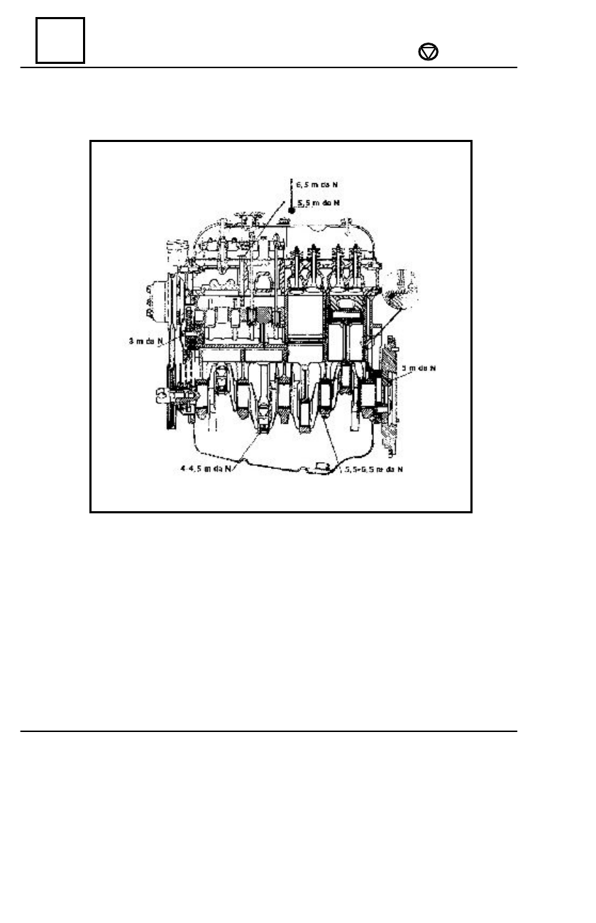
ENGINE AND LOWER ENGINE UNITS
TIGHTENING BY SCREWING UP MOMENTS