Chrysler Cirrus, Dodge Stratus, Plymouth Breeze Haynes. Manual - part 29


  Index      Manuals     Chrysler Cirrus, Dodge Stratus, Plymouth Breeze Haynes (1995-2000). Repair Manual


Search            


Content   ..  27  28  29  30   ..


Chrysler Cirrus, Dodge Stratus, Plymouth Breeze Haynes. Manual - part 29


10-4

Chapter 10 Suspension and steering systems

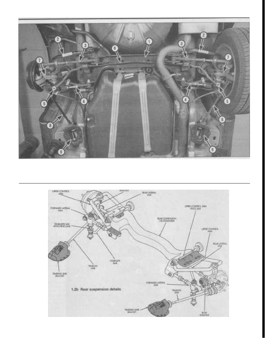
1.2a Rear suspension components

1

Crossmember

4

Forward lateral link

7

Rear knuckle

2

Upper control arm

5

Stabilizer bar attaching link

8

Trailing link

3

Rear lateral link

6

Stabilizer bar

9

Trailing link bracket

Chapter 10 Suspension

and

steering

systems

10-5

2.2b . . . and the attaching link assemblies from the lower control

arm (arrow)

2.2a Remove the nuts (arrow) .. .

a torch sometimes helps too, but isn't recom-
mended because of the obvious fire dangers.
Long breaker bars and extension, or
"cheater," pipes increase leverage, but never
use an extension pipe on a ratchet - the
ratcheting mechanism could be damaged.
Tightening the nut or bolt first will sometimes
help break it loose. Fasteners that require
drastic measures to remove should always
be replaced with new ones.

Most of the procedures in this Chapter

involve jacking up the vehicle and working
underneath it. A good pair of jackstands will
be needed. A hydraulic floor jack is the pre-

ferred type of jack to lift the vehicle, and it

can also be used to support certain compo-
nents during various operations. Warning:

Never rely on a jack to support a vehicle while

working on it. Whenever any of the suspen-

sion or steering fasteners are loosened or
removed they must 
be inspected and, if nec-
essary, replaced with new ones of the same
part number or of original equipment quality
and design. Torque specifications must be
followed for proper 
reassembly and compo-
nent retention. Never attempt to heat or
straighten any suspension or steering compo-
nents. Instead, replace any bent or damaged

part with a new one.

2

Stabilizer bar and bushings
(front) - removal, inspection and
installation

Removal

Refer to illustrations 2.2a, 2.2b and 2.3

1

Loosen the front wheel lug nuts, raise

the front of the vehicle and support it
securely on jackstands. Apply the parking

brake and block the rear wheels to keep the

vehicle from rolling off the stands. Remove
the front wheels.
2

Remove the nuts and the stabilizer bar

attaching link assemblies from the front lower
control arms (see Illustrations). Note: Use
an Allen wrench in the end of the lower con -

trol arm stud to prevent the stud from moving
when removing the attaching link nut.

3

Remove the four bolts attaching the sta-

bilizer bar bushing clamps to the front sus-
pension crossmember and body (see illus-

tration).
4

Remove the stabilizer bar from the vehi-

cle.

Inspection

5

Inspect for cracked, torn, or distorted

stabilizer bar bushings, bushing retainers,
and worn or damaged stabilizer bar attaching
li nks. Damaged stabilizer bar attaching links
must be replaced before reinstalling the sta-
bilizer bar.
6

To replace damaged stabilizer bar bush-

ings, open the bushing slit and peel the bush-
ing from the stabilizer bar. Caution: Install the

new bushings with the slits facing the same

way that the original bushing slits faced.

Installation

7

Position the stabilizer bar and bushings

in the front crossmember. Install the clamps
and bolts, tightening them to the torque listed
in this Chapter's Specifications.

8

Align the stabilizer bar attaching link

assemblies with the mounting holes in the

lower control arms and install the retaining
nuts. Tighten the nuts to the torque in this

Chapter's Specifications.
9

Install the wheels and lug nuts. Lower

the vehicle and tighten the lug nuts to the
torque listed in the Chapter 1 Specifications.

3

Shock absorber/coil spring
assembly (front) - removal,

inspection and installation

Removal

Refer to illustrations 3.3, 3.4, 3.5, 3.6, 3.7 and
3.9
Warning: Do not remove the shock absorber
rod nut before the shock absorber coil spring
is compressed.

2.3 Remove the stabilizer bar bushing

retainer bolts (arrows)

1

Loosen the wheel lug nuts, raise the

front of the vehicle, support it securely on
jackstands and remove the wheel.
2

Mark the shock absorbers with a R or L

if they are both removed at the same time.
3

Remove the wheel speed sensor cable

bracket from the steering knuckle (see illus-
tration).

3.3 Remove the wheel speed sensor

cable bracket from the steering knuckle

10

10-6

Chapter 10 Suspension and steering systems

3.5 Push the upper balljoint stud out of the steering knuckle

with a puller

3.4 Upper balljoint stud cotter pin and castle nut

BRACKET FLEX

HOSE

3.6 Remove the shock absorber clevis pinch bolt

3.7 Remove the bolt that attaches the shock absorber clevis to

the lower control arm

4

Remove the cotter pin and loosen the

castle nut from the upper balljoint stud (see
illustration).
5

Detach the balljoint from the steering

knuckle using a puller (see illustration).
Remove the nut and pull the steering knuckle

outward and to the back of the front wheel
opening. Caution: Be careful not to strain the
brake hose.

6

Remove the shock absorber clevis

pinch bolt and nut (see illustration).
7

Remove the clevis bolt from the lower

control arm (see illustration).
8

Use a soft-faced hammer (brass) to tap

the clevis from the shock absorber.

9

Remove the four bolts from the shock

tower attaching the upper control arm/shock

absorber (see illustration).

10

Remove the upper control arm mounting

bracket and shock absorber as an assembly.

11

Separate the upper control arm mount-

ing bracket and the shock absorber.

Inspection

12

Check the shock absorber assembly for

leaking fluid, dents, cracks and other obvious
damage which would warrant replacement.

SHOCK

TOWER

3.14 Proper positioning of the clevis on the shock absorber

3.9 Remove the four upper control arm/shock absorber mount

bolts from the shock tower (arrows)

SHOCK ABSORBER/

UPPER CONTROL ARM

MOUNTING BRACKET

BOLTS

CLEVIS MUST BE INSTALLED

FLUSH AGAINST LOCATING

TAB HERE

—COVER

Chapter 10 Suspension and steering systems

10-7

SHOCK ABSORBER ROD

UPPER ISOLATOR BUSHING

SHOCK ABSORBER

ASSEMBLY

VISE

SHOCK ABSORBER/CONTROL ARM

MOUNTING BRACKET

4.2 Clamp the shock absorber by the clevis in a vise

4.6 Remove the upper isolator bushing .. .

SHOCK ABSORBER/

CONTROL ARM

MOUNTING BRACKET

4.7 . . . and the lower isolator bushing and sleeve

4.8 Remove the washer and the dust shield from

the shock absorber

Check the coil spring for chips and corrosion.
Replace it if any undesirable symptoms are

found. See Section 4 for the shock absorber

or coil spring replacement procedure.

Installation

Refer to illustration 3.14
13

Connect the shock absorber assembly

to the upper control arm mount. Install the

assembly (with the clevis removed) into the
shock tower. Align the two locating pins and

the four mounting holes on the upper control

arm/shock absorber mount and tighten the

four bolts to the torque listed in this Chap-
ter's Specifications.

14 Install the clevis on the shock absorber.

Tap the clevis onto the shock absorber until it

is properly aligned and fully seated against

the locating tab on the shock absorber body

(see illustration). Install the bolt and tighten
it to the torque listed in this Chapter's Speci-

fications.

15 Install the clevis-to-lower control arm
bolt. Do not tighten it at this time.
16 Install the upper balljoint into the top of

the steering knuckle. Install the castle nut and
tighten it to the torque listed in this Chapter's
Specifications. Install a new cotter pin.

17 Install the speed control routing cable

on the steering knuckle.

18

Using a floor jack placed under the outer

end of the lower control arm, raise the lower

control arm to simulate normal ride height.
Tighten the shock absorber clevis-to-lower
control arm bolt to the torque in this Chap-
ter's Specifications. Remove the floor jack.
19 Install the wheel and lug nuts. Lower the
vehicle and tighten the lug nuts to the torque
li sted in the Chapter 1 Specifications.

4

Shock absorber/coil spring -
replacement

Warning: Disassembling a shock absorb-
er/coil spring assembly is dangerous. Use
only a high-quality spring 
compressor, which
can be rented at most auto parts stores or
equipment yards. Carefully follow all instruc-
tions furnished by the tool manufacturer or

serious injury could result.

Disassembly

Refer to illustrations 4.2, 4.6, 4.7, 4.8 and

4.10

1

Remove the shock absorber assembly

(see Section 3).
2

Reinstall the clevis bracket on the shock

absorber and tighten the pinch bolt. Clamp the
shock absorber in a vertical position in a vise
holding the clevis bracket (see illustration).
3

Compress the coil spring using a coil

spring compressor (which can be obtained at

most auto parts stores or equipment yards).
Follow the tool manufacturer's instructions,
install the spring compressor on the spring,
and compress it sufficiently to relieve all
pressure from the upper spring seat. Warn-
ing: 
Do not remove the shock absorber
damper rod nut before the coil spring is com-

pressed. Be sure to have the first full top and

bottom coil of the coil spring captured by the
coil spring compressor.
4

Remove the shock absorber damper rod

nut while holding the rod to prevent it from
rotating.
5

Remove the damper rod washer, the

upper control arm mounting bracket and the
isolator bushings from the damper rod.
6

Mark and remove the shock absorber

upper isolator bushing, and the lower isolator
bushing and sleeve from the upper control
arm mounting bracket. Then remove the
upper spring isolator from the mounting
bracket (see illustration).
7

Remove the lower isolator bushing from

the damper rod sleeve (see illustration).
8

Remove the washer from the top of the

dust shield and the dust shield from the
shock absorber assembly (see illustration).
9

Remove the compressed coil spring.

Warning: Keep the ends of the spring

pointed away from your body. Set the spring
aside in 
a safe, isolated location. Note: Mark

the springs R or L for proper reinstallation.

10

10-8

Chapter 10

Suspension

and steering systems

INSTALL ON SHOCK

ABSORBER ROD

IN THIS DIRECTION

SHOCK ABSORBER

ROD LOWER

ISOLATOR BUSHING

SHOCK ABSORBER ROD

UPPER ISOLATOR

BUSHING

INSTALL ON SHOCK

ABSORBER ROD

IN THIS DIRECTION

SLEEVE

JOUNCE

BUMPER

SHOCK ABSORBER

ROD

SHOCK ABSORBER

FLUID RESERVOIR

4.10 Remove the jounce bumper and sleeve from the

4.14 Upper and lower shock absorber rod bushing identification

shock absorber

10

Remove the jounce bumper and sleeve

from the shock absorber assembly (see illus-
tration).

11

Remove the coil spring isolator from the

lower spring seat on the shock absorber.

Inspection

12 Inspect the shock absorber for rod bind-
ing, and the shock mount and upper spring
seat/isolator for cracks/distortion, deteriora-
tion, rips and cracks. Check the coil spring
for chips, cracks and corrosion.
13

Replace any components found to be

worn or defective.

Assembly

Refer to illustration 4.14
14

Assembly is the reverse of disassembly.

When installing the sleeve on the shock
absorber rod, install it with the undercut side
of the sleeve facing downward. Caution: The
top and 
bottom shock absorber rod bushings
must be reinstalled on the rod exactly 
as they
were when they 
were removed (see illustra-
tion).
15 Install the shock absorber/coil spring
assembly (see Section 3).

5

Upper control arm (front) -
removal, inspection and
installation

Removal

1

Remove the shock absorber (see Sec-

tion 3).
2

Remove the coil spring from the shock

absorber (see Section 4).
3

Remove the nuts and bolts attaching the

upper control arm to the mounting bracket.
4

Remove the upper control arm from the

mounting bracket.

Inspection

5

Make sure the control arm is straight. If

it is bent, replace it. Do not attempt to

straighten a bent control arm.
6

Inspect the bushings in the mounting

bracket for cracks and tears. If any bushing is
torn or worn out, replace the control arm
mounting bracket.

Installation

7

Install the upper control arm on the

mounting bracket. Note: The bolt heads must
face inward (towards the coil spring). Tighten
the nuts to the torque listed in this Chapter's
Specifications.
8

Install the coil spring on the shock

absorber (see Section 4). Install the upper
shock mount/upper control arm assembly
(see Section 4). Install the shock absorber
(see Section 3).
9

Using a floor jack placed under the outer

end of the lower control arm, raise the lower
control arm to simulate normal ride height.
Tighten the shock absorber clevis-to-lower
control arm bolt to the torque in this Chap-
ter's Specifications. Remove the floor jack.
10 Install the wheel and lug nuts. Lower the
vehicle and tighten the lug nuts to the torque
listed in the Chapter 1 Specifications.

6

Lower control arm - removal and
installation

Removal

Refer to illustrations 6.4, 6.6, 6.12a and 6.12b

1

Loosen the wheel lug nuts, raise the

front of the vehicle, support it securely on
jackstands and remove the wheel.
2

Remove the brake caliper (see Chap-

ter 9) and support it with a piece of wire -
don't let it hang from the brake hose.
3

Remove the brake disc from the front

hub/bearing assembly.
4

If the vehicle is equipped with 15-inch

wheels, the balljoint heat shield must be
removed from the steering knuckle. Remove
the two bolts and the heat shield from the
steering knuckle (see illustration).
5

Remove the cotter pin and loosen the

lower balljoint castle nut a few turns.
6

Use a hammer to strike the boss on the

steering knuckle until it separates from the

lower balljoint stud (see illustration). Cau-

tion: Do not hit the lower control arm or the
balljoint 
grease seal, be careful not to sepa-

6.4 Remove the balljoint heat shield

6.6 Strike the boss on the steering

knuckle until it separates from the lower

balljoint stud

Chapter 10 Suspension and steering systems

10-9

6.12a Remove the nut/bolt attaching the rear of the lower control

arm to the front suspension crossmember .. .

6.12b . . . and the pivot bolt holding the front of the lower control

arm to the front suspension crossmember

rate the inner CV joint and do not pry the
lower balljoint from the steering knuckle.

Once the balljoint stud has been released

from the steering knuckle, remove the castle

nut.
7

Remove the shock absorber clevis-to-

lower control arm bolt and separate the clevis
from the lower control arm (see illustra-
tion 3.7).
8

Detach the stabilizer bar link from the

lower control arm (see Section 2).
9

Remove the bolts attaching the stabi-

lizer bar bushing clamp to the front suspen-
sion crossmember and the body of the vehi-
cle.
10

Lower one side of the stabilizer bar

away from the lower control arm.
11

Remove the nut and bolt attaching the

lower control arm to the front suspension
crossmember.

12

Remove the nuts and bolts attaching the

lower control arm to the front suspension
crossmember (see illustrations).

13

Separate the front of the lower control

arm from the front suspension crossmember.
Caution: Be careful not to damage the
balljoint 
seal against the steering knuckle
when lowering it from the crossmember.

14

Remove the rear of the lower control

arm from the front suspension crossmember.

Be careful to keep the rear bushing from
binding on the crossmember. Check the
bushings in the lower control arm for crack-
ing and other signs of deterioration. If neces-

sary, take the control arm to an automotive

machine shop to have the bushings replaced.

Installation

15 Install the rear, and then the front of the
lower control arm into the front suspension
cradle. Do not tighten the bolts at this time.
16

Connect the lower balljoint to the steer-

ing knuckle, tightening the castle nut to the

torque listed in this Chapter's Specifications.

Install a new cotter pin.
17 Installation of the remaining compo-
nents is the reverse of removal. Caution: Be

sure to install the balljoint heat shield. If the
heat shield is not installed, the boot may fail
due to excessive heat from the 
brake disc.

18

After installing the clevis on the lower

control arm, place a floor jack under the
lower balljoint and raise the lower control arm
to simulate normal ride height. Tighten the
lower control arm-to-crossmember bolts and
the shock absorber clevis-to-lower control
arm bolt/nut to the values listed in this Chap-
ter's Specifications.

19 Install the brake disc and caliper.

Tighten the caliper mounting bolts to the
torque listed in the Chapter 9 Specifications.
20 Install the wheel and lug nuts. Lower the
vehicle and tighten the lug nuts to the torque
li sted in the Chapter 1 Specifications.

7

Balljoints (front) - check

1

With the vehicle on the ground, reach

around the tire and try to wiggle the balljoint
grease fitting. If any movement is felt, the

balljoint is worn out.

2

Raise the vehicle and support it securely

on jackstands. Make sure the tires are not
contacting the ground.
3

Grasp the tire at top and bottom and try

to rock it in and out. Have an assistant feel for

play in the balljoints while you do this. The
balljoints on these vehicles are not supposed

to have any freeplay, so if any movement is

evident, the balljoint must be replaced.
4

The balljoints on these vehicles are not

HUB NUT

\

1

NUT LOCK

serviceable, nor can they be removed from
the control arms. If balljoint is bad, replace
the control arm (see Section 5).
5

The balljoint seal, however, is replace-

able. This is done by prying the old seal off
and pressing a new one into place with a
socket large enough to contact the outer cir-
cumference of the seal.
6

Remove the jackstands and lower the

vehicle.

Hub and bearing assembly (front)
- removal and installation

Removal

Refer to illustrations 8.1, 8.2 and 8.9
Warning: Dust created by the brake system
may contain 
asbestos, which is harmful to
your health. Never blow it out with com-
pressed air and don't inhale any of it. Do not,
under any circumstances, use petroleum-
based solvents to clean brake parts. Use
brake system 
cleaner only.

1

Remove the cotter pin, nut lock, and

spring washer from the front stub axle (see
illustration).
2

Loosen the driveaxle/hub nut (see illus-

tration). Note: The hub and driveshaft are
attached by splines through the steering

knuckle and retained by the hub nut.

8.2 Loosen the front hub nut

COTTER

PIN

RING

WASHER

8.1 Remove the cotter pin, nut lock, and

spring washer from the front stub axle

10

10-10

Chapter 10 Suspension and steering systems

10.2 Remove the nuts attaching the stabilizer links and isolator

bushings to the stabilizer

8.9 Pull the steering knuckle away from the outer CV joint

the brake disc.
18

Tighten all nuts/bolts to the torque listed

in this Chapter's Specifications.
19 Install the wheel and lug nuts. Lower the
vehicle and tighten the lug nuts to the torque
listed in the Chapter 1 Specifications.
20

Have an assistant apply the brakes, then

tighten the driveaxle/hub nut to the torque
listed in this Chapter's Specifications.

Removal and installation of the steering

knuckle is covered as part of the sequence in
Section 8.

10 Stabilizer bar and bushings (rear)

- removal and installation

Refer to illustrations 10.2 and 10.3

Removal

1

Loosen the rear wheel lug nuts. Raise

the rear of the vehicle and place it securely

on jackstands. Block the front wheels and
remove the rear wheels.

2

Remove the nuts attaching the stabilizer

li nks and isolator bushings to the stabilizer
(see illustration).

3

Unbolt the stabilizer bar clamps from

the crossmember (see illustration).
4

Remove the stabilizer bar from the vehi-

cle. Note: Take note of the orientation of the
stabilizer bar bend at the end of the bar
before removal for proper installation later -
the bend in the end of the bar is positioned
upwards in the vehicle when viewed from the
side. The stabilizer bar will 
come out of the
vehicle 
between the exhaust pipe and the
suspension crossmember.

Inspection

5

Inspect the stabilizer bushings for

cracks and tears. If the bushings are dam-
aged, distorted or excessively worn, replace
them.

3

Loosen the wheel lug nuts, raise the

vehicle and support it securely on jackstands.
Remove the wheel.
4

Remove the brake caliper, support it

with a piece of wire and remove the brake
disc from the hub (see Chapter 9).
5

Remove the balljoint heat shield from

the lower control arm on vehicles equipped
with 15-inch wheels (see illustration 6.4).
Note: 
The heat shield must be removed

before separating the balljoint stud from the
steering knuckle.

9

Steering knuckle - removal and

6

Separate the tie-rod end from the steer-

installation

ing knuckle arm (see Section 21).
7

Remove the speed sensor cable routing

bracket from the steering knuckle on vehicles
equipped with anti-lock brakes (see illustra-

tion 3.3).

8

Separate the steering knuckle from the

lower control arm balljoint (see Section 6).

9

Support the driveshaft and pull the

steering knuckle away from the outer C/V
joint (see illustration). If the driveaxle splines
stick in the hub, push the stub axle through
the hub with a two-jaw puller.

10

Remove the cotter pin and the nut from

the upper balljoint stud (see illustration 3.4).

11

Separate the upper balljoint stud from

the steering knuckle using a puller (see illus-
tration 3.5).

12

Mount the steering knuckle securely in a

vise.

13

Remove the hub/bearing mounting bolts

from the steering knuckle.

14

Remove the hub/bearing from the steer-

ing knuckle. It may be necessary to tap the
assembly out with a hammer.

Installation

15

Clean all hub/bearing mounting surfaces

on the steering knuckle.
16 Install the hub/bearing on the steering
knuckle. Install the bolts and tighten them to
the torque listed in this Chapter's Specifica-
tions.
17 Installation of the remaining compo-
nents is the reverse of removal. Caution: Be

sure to install the tie-rod and balljoint heat
shields. If the heat shields are not installed,

the seals may fail due to excessive heat from

Installation

6

Installation is the reverse of removal,

first tightening the stabilizer bar ends to the
torque listed in this Chapter's Specifications,
then installing the bushing clamps. Make
sure the rubber bushings are installed with
the slits in the bushings positioned toward

the front of the vehicle. Tighten the stabilizer

bushing clamp bolts to the torque listed in

this Chapter's Specifications.

7

Install the rear wheels and lug nuts.

Lower the vehicle and tighten the lug nuts to

the torque listed in the Chapter 1 Specifica-
tions.

11 Shock absorber/coil spring

assembly (rear) - removal,

inspection, component
replacement and installation

Removal

Refer to illustrations 11.2 and 11.4

1

Inside the trunk, roll back the carpeting

on the top of the rear shock absorber tower
to access the upper shock mounting bolts.
Remove the plastic cap.

10.3 The stabilizer bar bushing clamps

are secured with two bolts (arrows)

Chapter 10 Suspension and

steering systems

10-11

SHOCK ABSORBER

ROD

11.2 Lift the carpeting and unsnap the

plastic cover from the upper shock tower,

then remove the two upper mounting

bolts (arrows)

11.4 Remove the lower shock mount

clevis bolt and nut (arrow)

11.13 Remove the washer on the top of

the shock absorber assembly

SHOCK ABSORBER

ROD

ISOLATOR

BUSHING

SHOCK

ABSORBER

MOUNT

SPRING

ISOLATOR

11.14a Remove the isolator bushing and shock absorber mount

11.14b Remove the spring isolator from the coil spring

2

Inside the trunk, remove the two shock

absorber upper mounting nuts (see illustra-

tion). Note: Do not remove the shock damper
rod nut at the center of the upper mount.

3

Loosen the rear wheel lug nuts, raise the

rear of the vehicle and support it securely on

jackstands. Block the front wheels and

remove the rear wheels.
4

Remove the shock absorber lower

mounting bolt from the rear knuckle (see
illustration).
5

Push down on the rear suspension and

pull the shock away from the knuckle. Then
guide the shock downward and remove the
shock absorber.

Inspection

6

Check the shock absorber for leaking

fluid, dents, cracks and other obvious dam-

age which would require repair or replace-
ment. To check for loss of gas charge,
remove the coil spring (see Step 10) push the
shaft of the shock in, then release - the shaft
should return to its fully extended position.
7

Check the coil spring for chips or cracks

in the spring coating (this can cause prema-

ture spring failure due to corrosion). Inspect
the spring seat for general deterioration.

8

Inspect the rubber isolators and bush-

ings in the upper mount bracket for cracks,

distortion, or any deterioration. Inspect the
dust shield for rips or deterioration. Inspect
the jounce bumper for cracks and deteriora-
tion.
9

Replace components as necessary.

Component replacement

Refer to illustrations 11.13, 11.14a, 11.14b,

11.15 and 11.18

Warning: Disassembling a shock absorb-
er/coil spring assembly is dangerous. Use
only a high-quality spring compressor, which
can be rented 
at most auto parts stores or
equipment yards. Carefully follow all instruc-
tions furnished by the 
tool manufacturer or
serious injury could result.
10

Mount the shock assembly in a vise,

clamping the bottom shock clevis bracket.
Mark the shock absorber and the coil spring
RIGHT or LEFT, depending on which side of
the vehicle from which it was removed.
Warning: Do not remove the shock damper
rod nut before the spring is compressed.
11

Installing the spring compressor on the

first full top and bottom coil of the spring,
compress the spring until it can be wiggled,
indicating that all pressure has been relieved
from the upper mount.
12

Hold the damper rod from rotating using

a wrench or locking pliers, then unscrew the

11.15 Remove the rod washer from the

10

top of the shock absorber dust boot

damper rod nut.

13

Remove the washer from the shock

mounting bracket (see illustration).

14

Remove the isolator bushing, the shock

absorber mount, and the spring isolator from
the coil spring (see illustrations).

15

Remove the rod washer from the top of

the shock absorber dust boot (see illustra-
tion).


Content   ..  27  28  29  30   ..