Chrysler Cirrus, Dodge Stratus, Plymouth Breeze Haynes. Manual - part 14


  Index      Manuals     Chrysler Cirrus, Dodge Stratus, Plymouth Breeze Haynes (1995-2000). Repair Manual


Search            


Content   ..  12  13  14  15   ..


Chrysler Cirrus, Dodge Stratus, Plymouth Breeze Haynes. Manual - part 14


2C-10

Chapter 2 Part C General engine overhaul procedures

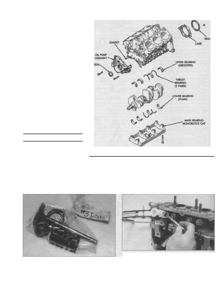
9.5c Engine block components - V6 engine

Water pump
Cylinder head(s)
Oil pan and oil pickup tube
Oil pump
Balance shaft carrier (2.4L four-cylinder

engine)

Piston/connecting rod assemblies
Crankshaft

6

Before beginning the disassembly and

overhaul procedures, make sure the following

items are available. Also, refer to Engine

overhaul - reassembly sequence for li st of
tools and materials needed for engine

reassembly.

Common hand tools

Small cardboard boxes or plastic bags

for storing parts

Gasket scraper
Ridge reamer
Micrometers

Telescoping gauges

Dial indicator set

Valve spring compressor

Cylinder surfacing hone
Piston ring groove cleaning tool
Electric drill motor
Tap and die set

Wire brushes

Oil gallery brushes
Cleaning solvent

10 Cylinder head - disassembly

Refer to illustrations 10.2, 10.3, 10.4a, 10.4b

and 10.4c

Note: New and rebuilt cylinder heads are
commonly available for most engines at deal-
erships and auto parts stores. Due to the fact
that some specialized tools are necessary for
the disassembly and inspection procedures,

and replacement parts may not be readily
available, it may be more practical and eco-
nomical for the home mechanic to purchase a
replacement head rather than taking the time

to disassemble, inspect and recondition the

original.

1

Cylinder head disassembly involves

removal of the intake and exhaust valves and
related components. If they're still in place,
remove the rocker arm shafts and camshaft,
on the SOHC engine (refer to the appropriate
Part of Chapter 2) or the bearing caps,
camshafts, rocker arms and lash adjusters,
on the DOHC engine (see Chapter 2A). Label

the parts or store them separately so they
can 
be reinstalled in their original locations.
2

Before the valves are removed, arrange

to label and store them, along with their
related components, so they can be kept
separate and reinstalled in the same valve
guides they are removed from (see illustra-
tion).

10.2 A small plastic bag with an appropriate label can be used to

store the valvetrain components so they don't get mixed up

10.3 After compressing the valve spring, use a magnet (shown) or

needle-nose pliers to extract the valve keepers - a valve spring
compressor adapter, such as the one shown, will be needed to

compress the valve spring on this type of cylinder head

Chapter 2 Part C General engine overhaul procedures

2C-11

10.4a Remove the valve from the

cylinder head .. .

3

Compress the springs on the first valve

with a spring compressor and remove the

keepers (see illustration). Carefully release

the valve spring compressor and remove the

retainer and the spring.

4

Pull the valve out of the head, then

remove the valve stem seal with pliers and

withdraw spring seat from the guide (see
illustrations). Note: 
On the four-cylinder
engines the valve stem seal and spring seat
are an assembly. 
If the valve binds in the
guide (won't pull through), push it back into
the head and deburr the area around the
keeper groove and step tip with a fine file or
whetstone (see illustration).
5

Repeat the procedure for the remaining

valves. Remember to keep all the parts for
each valve together so they can be rein-
stalled in the same locations.
6

Once the valves and related compo-

nents have been removed and stored in an
organized manner, the head should be thor-
oughly cleaned and inspected. If a complete
engine overhaul is being performed, finish the
engine disassembly procedures before
beginning the cylinder head cleaning and
inspection process.

10.4b . . . then use pliers to remove the

valve stem seal from the valve guide

11

Cylinder head - cleaning and
inspection

1

Thorough cleaning of the cylinder head

and related valvetrain components, followed

by a detailed inspection, will enable you to

decide how much valve service work must be

performed during the engine overhaul. Note:

If the engine was severely overheated, the
cylinder head is probably warped.

Cleaning

2

Scrape all traces of old gasket material

and sealing compound off the head gasket,
intake manifold and exhaust manifold sealing
surfaces. Caution: The cylinder head is alu-
minum, be very careful not to gouge 
the seal-
ing surfaces. Special gasket removal solvents
that soften gaskets and make removal much
easier are available at auto parts stores.
3

Remove all built-up scale from the

coolant passages.
4

Run a stiff wire brush through the vari-

ous holes to remove deposits that may have

formed in them.

5

Run an appropriate size tap into each of

the threaded holes to remove corrosion and
thread sealant that may be present. If com-
pressed air is available, use it to clear the
holes of debris produced by this operation.

Warning: Wear eye protection when using
compressed 
air!

6

Clean the cylinder head with solvent and

dry it thoroughly. Compressed air will speed

the drying process and ensure that all holes
and recessed areas are clean. Note: Decar-
bonizing chemicals are available and may
prove very useful when cleaning cylinder
heads and valve train components. They are
very caustic and should 
be used with caution.
Be sure to follow the instructions on the con-
tainer.
7

Clean the rocker arms hydraulic lash

adjusters, spacers and shafts with solvent.
Note: The lash adjusters and rocker arms on
SOHC engines are precision assemblies, be
careful not 
to mix-up parts when cleaning. Dry
all parts thoroughly (don't mix them up during
the cleaning process). Compressed air will
speed the drying process and can be used to
clean out the oil passages. Warning: Wear
eye protection when using compressed air!
8

Clean all the valve springs, spring seats,

keepers and retainers with solvent and dry
them thoroughly. Clean the components one
valve at a time to avoid mixing up the parts.
9

Scrape off any heavy deposits that may

have formed on the valves, then use a motor-
ized wire brush to remove deposits from the

valve heads and stems. Warning: Wear eye
protection when using a motorized wire
brush! 
Again, make sure the valves don't get

mixed up.

Inspection

Note: Be sure to perform all of the following

inspection procedures before concluding that
machine shop work is required. Make a list of
the items that need attention.

Cylinder head

Refer to illustrations 11.10, 11.11 and 11.13
10 Inspect the head very carefully for
cracks, evidence of coolant leakage and

2C

10.4c If the valve stem won't pass through the guide, chances are

its because of a burr or raised material on the end of the valve

stem. Use a fine file or whetstone to deburr the valve

stem as required

11.10 Inspect the cylinder head internal passages for cracks or

other defects

2C-12

Chapter 2 Part C General engine overhaul procedures

11.11 Measure the cylinder head gasket surface(s) flatness and

compare to the limits listed in this Chapter's Specifications

11.13 Checking valve stem-to-guide clearance - remember to

divide the measurement by 2 to obtain the correct dimension

VALVE STEM TIP

11.16 Measure the valve margin of

each valve

11.17 Measuring the valve spring

free length

11.15 Carefully inspect the areas

indicated for wear or damage

other damage (see illustration). If cracks are

found, check with an automotive machine

shop concerning repair. If repair isn't possi-
ble, a new cylinder head must be obtained.
11

Using a straightedge and feeler gauge,

check the head gasket mating surface (see
illustration). 
Check the intake and exhaust
manifold surfaces on the cylinder head also.
If the warpage on any of the surfaces
exceeds the limits listed in this Chapter's
Specifications, they can be resurfaced at an
automotive machine shop.
12

Examine the valve seats in each of the

combustion chambers. If they're pitted,
cracked or burned, the head will require valve
service that's beyond the scope of the home
mechanic.
13

Check the valve stem-to-guide clear-

ance, using a clamping dial indicator base
attached securely to the head, by measuring

the lateral movement of the valve stem inside
the valve guide (see illustration). The valve

must be in the guide and approximately 1/16-
inch off the seat. The total valve stem move-
ment indicated by the gauge needle must be

divided by two to obtain the actual clearance.

14

After this is done, if there's still some

doubt regarding the condition of the valve
guides they should be checked by an auto-
motive machine shop (the cost should be
minimal).

Valves

Refer

to illustrations

11.15

and

11.16

15

Carefully inspect each valve face for

uneven wear, deformation, cracks, pits and
burned areas (see illustration). Check the
valve stem for scuffing and galling and the
neck for cracks. Rotate the valve and check
for any obvious indication that it's bent. Look
for pits and excessive wear on the end of the
stem. The presence of any of these condi-
tions indicates the need for valve service by
an automotive machine shop.
16

Measure the margin width on each valve

(see illustration). Any valve with a margin
narrower than listed in this Chapter's Specifi-
cations will have to be replaced.

Valve components

Refer

to illustrations 11.17 and 11.18

17

Check each valve spring for wear (on

the ends) and pits. Measure the free length
(see illustration) and compare it to the value
li sted in this Chapter's Specifications. Any
springs that are shorter than specified have
sagged and should not be reused. The ten -

11.18 Check each valve spring

for squareness

sion of all springs should be checked with a
special fixture before deciding that they're
suitable for use in a rebuilt engine (take the
springs to an automotive machine shop for
this check).
18

Stand each spring on a flat surface and

check it for squareness (see illustration). If
any of the springs are distorted or sagged,
replace all of them with new parts.

Chapter 2 Part C General engine overhaul procedures

2C-13

13.4a On four-cylinder models, the valve seal and spring seat are

an assembly

13.4b Install the valve stem seal using an appropriate size socket

and hammer

19

Check the spring retainers and keepers

for obvious wear and cracks. Any question-

able parts should be replaced with new ones,
as extensive damage will occur if they fail
during engine operation.

Rocker arm components

20

Refer to the appropriate Part of Chapter

2 for the rocker arm and hydraulic lash
adjusters inspection procedures.
21

Any damaged or excessively worn parts

must be replaced with new ones.

22 If the inspection process indicates that
the valve components are in generally poor
condition and worn beyond the limits speci-
fied, which is usually the case in an engine
that's being overhauled, reassemble the
valves in the cylinder head and refer to Sec-
tion 12 for valve servicing recommendations.

12 Valves - servicing

1

Because of the complex nature of the

job and the special tools and equipment

needed, servicing of the valves, the valve
seats and the valve guides, commonly known
as a valve job, should be performed by an
experienced professional.
2

The home mechanic can remove and

disassemble the head, do the initial cleaning
and inspection, then reassemble and deliver
it to a dealer service department or an auto-
motive machine shop for the actual service

work. Doing the inspection will enable you to
see what condition the head and valvetrain
components are in and will ensure that you

know what work and new parts are required

when dealing with an automotive machine
shop.
3

The dealer service department, or auto-

motive machine shop, will remove the valves
and springs, recondition or replace the valves
and valve seats, recondition the valve guides,
check and replace the valve springs, spring
retainers and keepers (as necessary), replace
the valve seals with new ones, reassemble
the valve components and make sure the
installed spring height is correct. The cylinder
head gasket surface will also be resurfaced if

13.6a Install the spring over the valve

guide and onto the seat .. .

it's warped.
4

After the valve job has been performed

by a professional, the head will be in like-new
condition. When the head is returned, be sure
to clean it again before installing it on the
engine to remove any metal particles and
abrasive grit that may still be present from
the valve service or head resurfacing opera-
tions (which happens frequently). Use com-
pressed air, if available, to blow out all the oil
holes and passages.

13 Cylinder head - reassembly

Refer to illustrations 13.4a, 13.4b, 13.6a,

13.6b, 13.7 and 13.9
1

Regardless of whether or not the head

was sent to an automotive repair shop for
valve servicing, make sure it's clean before

beginning reassembly.

2

If the head was sent out for valve servic-

ing, the valves and related components will

already be in place. Begin the reassembly
procedure with Step 8.
3

If the valve faces or seats have been

ground on a 2.0L four-cylinder engine, mea-
sure the valve stem tip-to-spring seat surface
height (without spring or seat installed) (see

13.6b . . . and place the retainer onto

the spring

illustration 13.9 Dimension "A"). If the
dimension is greater than the tolerance listed
in this Chapter's Specifications, grind the
valve stem as required to achieve the correct
dimension.

4

Install the spring seats and new valve

stem seals (V6 engines) or the new valve
seal/spring seat assembly (four-cylinder
engines) onto each of the valve guides (see

illustration). Note: On V6 engines, install the

silver colored valve stem seals onto the intake
valve guides and the black 
colored valve stem
seals onto the exhaust valve guides. Using a
hammer and a deep socket or seal installa-
tion tool, gently tap each valve stem
seal/spring seat assembly into place until it's
completely seated on the guide (see illustra-
tion). 
Don't twist or cock the seals during
installation or they won't seal properly on the
valve stems.
5

Beginning at one end of the head, apply

moly-based grease or clean engine oil to the
valve stem and install the first valve.
6

Install spring over the valve guide and

set the spring and retainer in place (see illus-
trations). Note: 
On V6 engines, install the
valve springs with the enameled end up.
7

Compress the spring with a valve spring

compressor and carefully install the keepers
in the upper groove, then slowly release the

2C

2C-14

Chapter 2 Part C General engine overhaul procedures

13.7 Apply a small dab of grease to each

keeper as shown here - it will hold them in

place on the valve stem as the spring

is released

compressor and make sure the keepers seat
properly. Apply a small dab of grease to each
keeper to hold it in place if necessary (see
illustration).
8

Repeat the procedure for the remaining

14.1 Before you try to remove the pistons,

use a ridge reamer to remove the raised

material (ridge) from the top of

the cylinders

13.9 Valve stem tip-to-spring
seat surface (Dimension "A" -

2.0L four-cylinder engines

only) and installed spring

height (Dimension "B" -

all engines)

valves. Be sure to return the components to

their original locations - don't mix them up!

9

Measure the installed valve spring

height (Dimension "B") with a vernier or dial
caliper (see illustration). If the head was sent
out for service work, the installed height
should be correct, but don't automatically
assume that it is. If the height is greater than
li sted in this Chapter's Specifications, shims

can be added under the spring seat to cor-

rect it. Caution: Do not shim the springs to

the point where the installed height is less

than specified.
10

Refer to the appropriate Part of this

Chapter for the procedure to install the
camshaft(s) and rocker arms.

14 Pistons and connecting rods -

removal

Refer to illustrations 14.1, 14.3 14.4 and 14.6
Note: Prior to removing the piston/connect-
ing rod assemblies, remove the cylinder head
and oil pan by referring to the appropriate
Part of this Chapter.

1

Use your fingernail to feel if a ridge has

formed at the upper limit of ring travel (about
1/4-inch down from the top of each cylinder).
If carbon deposits or cylinder wear have pro-
duced ridges, they must be completely
removed with a special tool (see illustration).

Follow the manufacturer's instructions pro-
vided with the tool. Failure to remove the
ridges before attempting to remove the pis-
ton/connecting rod assemblies may result in
piston breakage.
2

After the cylinder ridges have been

removed, turn the engine so the crankshaft is
facing up.
3

Before the main bearing cap assembly

and connecting rods are removed, check the
connecting rod endplay with feeler gauges.
Slide them between the first connecting rod
and the crankshaft throw until the play is
removed (see illustration). The endplay is
equal to the thickness of the feeler gauge(s).
If the endplay exceeds the service limit, new
connecting rods will be required. If new rods
(or a new crankshaft) are installed, the end-
play may fall under the minimum listed in this
Chapter's Specifications (if it does, the rods
will have to be machined to restore it - con-
sult an automotive machine shop for advice if
necessary). Repeat the procedure for the
remaining connecting rods.

4

Check the connecting rods and caps for

identification marks (see illustration). If they
aren't plainly marked, use a small center-
punch to make the appropriate number of
indentations on each rod and cap (1, 2, 3,

etc., depending on the cylinder they're asso-
ciated with).
5

Loosen each of the connecting rod cap

nuts or bolts 1/2-turn at a time until they can

14.3 Checking the connecting rod endplay (side clearance)

14.4 If the connecting rods and caps are not identified, use a

center punch or numbered impression stamps to mark the caps

to the rods by cylinder number (No. 4 connecting rod shown)

Chapter 2 Part C General engine overhaul procedures

2C-15

14.6 On V6 engines, place a section of plastic or rubber hose over

the connecting rod studs to prevent damaging the crankshaft

journals during piston/rod removal

be removed by hand. Remove the number
one connecting rod cap and bearing insert.
Don't drop the bearing insert out of the cap.
6

If you are removing the rods from a V6

engine, slip a short length of plastic or rubber
hose over each connecting rod stud to pro-

tect the crankshaft journal and cylinder wall
as the rod is removed (see illustration).

7

Remove the bearing insert and push the

connecting rod/piston assembly out through
the top of the engine. Use a wooden or plastic

hammer handle to push on the upper bearing

surface in the connecting rod. If resistance is
felt, double-check to make sure that all of the
ridge was removed from the cylinder.
8

Repeat the procedure for the remaining

cylinders. Note: On four-cylinder engines,
new connecting rod bolts must be installed
when the engine is reassembled.
9

After removal, reassemble the connect-

ing rod caps and bearing inserts in their
respective connecting rods and install the
cap bolts finger tight. Leaving the old bearing
inserts in place until reassembly will help pre-
vent the connecting rod bearing surfaces
from being accidentally nicked or gouged.
10

Don't separate the pistons from the

connecting rods (see Section 20 for addi-
tional information).

interconnected through two gears which
rotate them in opposite directions. These
gears are driven by a chain from the crank-
shaft and they are designed to rotate at a 2:1
ratio with the crankshaft (one turn of the
crankshaft equals two turns of the balance
shafts). This motion will counterbalance cer-
tain reciprocating masses within the engine.
2

Remove the chain cover, guide and ten-

sioner from the engine block (see illustra-

tion).

3

While keeping the crankshaft from rotat-

ing, remove the balance shaft bolts. Caution:

If the rocker arm shaft assemblies have not
been removed, DO NOT 
rotate the crankshaft
as valve damage could occur. Note: block
of wood placed tightly between the engine
block and the crankshaft counterbalance will
prevent crankshaft rotation.
4

Remove the balance shaft chain

sprocket, chain and crankshaft chain sprock-

et (see illustration). Use two prybars to work
the sprocket back and forth until it is free
from the crankshaft. Note: The carrier assem-
bly may be removed from the main bearing
cap assembly at this time, if balance shaft
removal is not required.
5

Remove the special stud (double-ended)

15.4 Balance shaft chain, crankshaft and
balance shaft sprockets assembly details

from the gear cover. Then remove the gear
cover and balance shaft drive and driven
gears (see illustration).

2C

15 Balance shafts (2.4L four-cylinder

engine only) - removal,
inspection and installation

Note: This procedure assumes that the
engine has been removed from the vehicle

and the driveplate, timing belt, oil pan and oil
pump 
have also been removed (see Chapter
2, Part A).

Removal

Refer to illustrations 15.2, 15.4, 15.5 and 15.6
1

The balance shafts are installed in a car-

ri er that is mounted to the main bearing cap
assembly on the lower part of the engine
block (see illustration 9.5b). The shafts are

15.5 Remove the double
ended stud and separate

the gear cover from the

balance shaft carrier

2C-16

Chapter Part General engine overhaul procedures

15.6 Remove the rear cover from the

carrier and withdraw the balance shafts

6

Remove the rear cover from the carrier

and withdraw the balance shafts (see illus-
tration).
7

Remove the bolts that retain the carrier

to the main bearing cap assembly, and sepa-
rate the carrier from the engine.

Inspection

8

Clean all components with solvent and

dry thoroughly. Inspect all components for
damage and wear. Pay special attention to
the chain, sprocket and gear teeth and the
bearing surfaces of the carrier and balance
shafts. Replace defective parts as necessary.

15.12 After gear installation,

the balance shaft keyways

should be parallel and facing

the crankshaft, and the gear

alignment marks should be

together as shown

Installation

Refer to illustrations 15.12

and

15.15

9

Install the balance shaft carrier onto the

main bearing cap assembly and tighten the
bolts to the torque listed in this Chapter's
Specifications.

10

Lubricate the balance shafts with clean

engine oil and insert them into the carrier.

11

Install the rear cover and tighten the

bolts to the torque listed in this Chapter's

Specifications.

12

Rotate the balance shafts until both

shaft keyways are parallel and facing toward
the crankshaft. Install the short hub drive
gear on the sprocket driven shaft and the

long hub gear on the gear driven shaft. After
installation, the timing marks (dots) should be

together and the keyways positioned as

shown (see illustration).
13 Install the gear cover and tighten the
double-ended stud to the torque listed in this
Chapter's Specifications.
14 Install the sprocket onto the crankshaft
with the timing mark facing out, be careful

not to cock the sprocket as its being
installed.
15

Position the crankshaft so the timing

mark on the chain sprocket is aligned with
the parting line on the left side of the num-
ber 1 main bearing cap as shown (see illus-
tration).
16

Place the chain onto the crankshaft

sprocket so that the nickel plated link of the
chain is located at the timing mark on the
crankshaft sprocket (see illustration 15.15).
17 Install the balance shaft sprocket into
the chain so that the timing mark on the
sprocket (yellow dot) mates with the nickel
plated link on the chain (8 links from the
upper nickel plated link) (see illustration

15.15).
18

Slide the balance shaft sprocket onto

the balance shaft. If the sprocket is difficult to

install on the balance shaft, it may be neces-

sary to loosen the rear cover and push the

balance shaft slightly out of the carrier to

facilitate sprocket installation. Note: The tim-

ing

mark

on

the

balance

shaft sprocket and

INSTALL CHAIN WITH

ALL KEYWAYS UP

LOWER NICKEL

PLATED LINK 8 LINKS

FROM UPPER LINK

15.15 The timing mark on the crankshaft sprocket, nickel plated

links, notch and the yellow dot on balance shaft sprocket must be

aligned for correct timing

15.20 With the shim in place, apply approximately 5.5 to 6.5 Ibs of

pressure to the chain tensioner and then tighten the bolt to the

torque listed in this Chapter's Specifications

Chapter 2 Part C General engine overhaul procedures

2C-17

16.1 Checking the crankshaft endplay using a dial indicator

16.3 Checking the crankshaft endplay using feeler gauges at the

thrust bearing journal

the nickel plated link should align with the
notch on the side of the gear 
cover (see illus-
tration 15.15).

19 Install the balance shaft bolts. While

keeping the crankshaft from rotating, tighten
the balance shaft bolts to the torque listed in
this Chapter's Specifications. Note: block
of wood placed tightly between the engine
block and the crankshaft counterbalance will
prevent crankshaft rotation.

Chain tensioning

Refer to illustration 15.20
20 Install the chain tensioner loosely. Place
a 0.039 x 2.75 inch shim (a feeler gauge cut
to the appropriate size can be used) between
the tensioner and the chain (see illustration).
Push the tensioner up against the chain.
Apply firm pressure (approximately 5.5 to 6.5
Ibs) directly behind the adjustment slot to
remove the slack.
21

With pressure applied, tighten the top

tensioner bolt first then the bottom pivot bolt.

Tighten the bolts to the torque listed in this

Chapter's Specifications. Remove the shim.
22

Place the chain guide onto the double-

ended stud making sure the tab on the guide

fits into the slot on the gear cover. Tighten
the nut to the torque listed in this Chapter's

Specifications.
23 Install the chain cover and tighten the
bolts securely.

16 Crankshaft - removal

Refer to illustrations 16.1 and 16.3

Note: The crankshaft can be removed only

after the engine has been removed from the
vehicle. It's assumed that the driveplate,
crankshaft pulley, timing belt, oil pan, oil
pump body, oil filter and piston/connecting
rod assemblies have already been removed.
On V6 engines, the rear main oil 
seal retainer
must 
be unbolted and separated from the
block before proceeding with crankshaft
removal.

1

Before the crankshaft is removed, mea -

sure the endplay. Mount a dial indicator with

the indicator in line with the crankshaft and
just touching the end of the crankshaft as

shown (see illustration).

2

Pry the crankshaft all the way to the rear

and zero the dial indicator. Next, pry the

crankshaft to the front as far as possible and
check the reading on the dial indicator. The
distance traveled is the endplay. If it's greater
than the tolerance listed in this Chapter's
Specifications, check the crankshaft thrust
surfaces for wear after its removed. If no
wear is evident, new main bearings should
correct the endplay.
3

If a dial indicator isn't available, feeler

gauges can be used. Gently pry the
crankshaft all the way to the front of the
engine. Slip feeler gauges between the
crankshaft and the front face of the thrust
bearing or washer to determine the clearance
(see illustration).
4

Loosen the main bearing cap assembly

bolts 1/4-turn at a time each, until they can
be removed by hand.
5

Gently tap the main bearing cap assem-

bly with a soft-face hammer around the
perimeter of the assembly. Pull the main
bearing cap assembly straight up and off the

cylinder block. On 2.0L four-cylinder engines,
remove the oil filter passage 0-ring seal and
the three main bearing cap assembly locating
dowels. Try not to drop the bearing inserts if
they come out with the assembly.
6

Carefully lift the crankshaft out of the

engine. It may be a good idea to have an
assistant available, since the crankshaft is
quite heavy and awkward to handle. With the
bearing inserts in place inside the engine
block and main bearing caps, reinstall the
main bearing cap assembly onto engine
block and tighten the bolts finger tight. Make
sure you install the main bearing cap assem-
bly on V6 models with the arrow facing the
front (timing belt end) of the engine.

17 Engine block - cleaning

Refer to illustrations 17.1a, 17.lb, 17.8 and

17.10
1

Remove the core plugs from the engine

block. To do this, knock one side of the plugs
into the block with a hammer and a punch,

then grasp them with large pliers and pull
them out (see illustrations).

17.1a Use a hammer and a large punch to

17.lb . . . then pull the core plugs

knock the core plugs sideways in

their bores .. .

out with pliers

2C


Content   ..  12  13  14  15   ..