Peugeot 205 (954 cc, 1124 cc, 1360 cc, 1580 cc & 1905 cc). Manual - part 22
7 If necessary, the intermediate shaft can be
removed after prising out the grommet and
unscrewing the bottom clamp bolt (see
illustration).
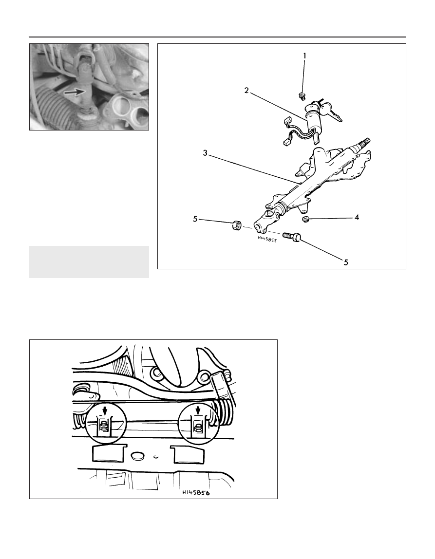
8 To remove the steering lock, unscrew the
retaining bolt then, with the ignition key
aligned with the small arrow between the ‘A’
and ‘M’ positions, depress the plunger in the
housing and withdraw the lock (see
illustration).
Refitting
9 Refitting is a reversal of removal.
15 Steering gear - removal and
refitting
4
Manual steering gear
Removal
1 Chock the rear wheels then jack up the
front of the car and support it on axle stands
(see “Jacking and vehicle support”). Remove
the front roadwheels.
2 Unscrew the track rod end locknuts then
use a separator tool to detach the track rod
end balljoints from the hub carrier steering
arms.
3 Mark the lower column in relation to the
pinion on the steering gear.
4 Unscrew and remove the column-to-pinion
clamp bolt.
5 Unscrew and remove the two mounting
bolts and withdraw the steering gear from one
side of the subframe (see illustration).
Refitting
6 Refitting is a reversal of removal, but tighten
all nuts and bolts to the specified torque. On
completion, have the front wheel toe setting
checked (see Section 21).
Power-assisted steering gear
Removal
7 Chock the rear wheels then jack up the
front of the car and support it on axle stands
(see “Jacking and vehicle support”). Remove
the front roadwheels.
8 Prepare a suitable container, then
disconnect the fluid pipes from the steering
gear, and allow the fluid to drain into the
container.
9 Unscrew the track rod end balljoint
locknuts, then use a separator tool to detach
the track rod end balljoints from the hub
carrier steering arms.
10 Mark the lower column in relation to the
pinion on the steering gear.
11 Unscrew and remove the
column-to-pinion clamp bolt.
12 On manual transmission models,
disconnect the three gearchange control rods
from the levers on the transmission.
13 Extract the spring clip from the
gearchange linkage (see illustration), then
unclip the transmission selector and
10•8 Suspension and steering
14.7 Steering column intermediate shaft
(arrowed)
14.8 Steering column and lock assembly
components
1 Bolt
2 Steering lock and ignition
switch
3 Steering column
4 Mounting nut
5 Clamp bolt and nut
15.5 Steering gear mounting bolt locations (arrowed)