Peugeot 205 (954 cc, 1124 cc, 1360 cc, 1580 cc & 1905 cc). Manual - part 18


  Index      Manuals     Peugeot 205 Haynes (954 cc, 1124 cc, 1360 cc, 1580 cc & 1905 cc). Repair Manual


Search            


Content   ..  16  17  18  19   ..


Peugeot 205 (954 cc, 1124 cc, 1360 cc, 1580 cc & 1905 cc). Manual - part 18


Refitting

Refitting is a reversal of removal, but first
insert all mounting bolts finger tight, then
tighten the flywheel end bolts followed by the
brush end bolts.

10 Starter motor - testing and

overhaul

5

If the starter motor is thought to be suspect,

it should be removed from the vehicle and
taken to an auto-electrician for testing. Most
auto-electricians will be able to supply and fit
brushes at a reasonable cost. However, check
on the cost of repairs before proceeding as it
may prove more economical to obtain a new
or exchange motor.

11 Ignition switch - removal and

refitting

4

The ignition switch is integral with the

steering column lock, and can be removed as
described in Chapter 10.

12 Oil pressure warning light

switch - removal and refitting

2

Removal

The switch is located at the front of the
cylinder block, above the oil filter mounting.
Note that on some models access to the
switch may be improved if the vehicle is
jacked up and supported on axle stands so
that the switch can be reached from
underneath (see “Jacking and vehicle
support”
).
Disconnect the battery negative lead.
Remove the protective sleeve from the
wiring plug (where applicable), then
disconnect the wiring from the switch.
Unscrew the switch from the cylinder block,
and recover the sealing washer. Be prepared
for oil spillage, and if the switch is to be left
removed from the engine for any length of
time, plug the hole in the cylinder block.

Refitting

Examine the sealing washer for signs of
damage or deterioration and if necessary
renew.
Refit the switch, complete with washer, and
tighten it securely. Reconnect the wiring
connector.
Lower the vehicle to the ground then check
and, if necessary, top-up the engine oil as
described in “Weekly checks”.

13 Electronic oil level sensor -

general information

Some 1985 XU series engine models have
an oil level sensor fitted to the engine sump,
together with a warning lamp on the
instrument panel. The system was only fitted
on the 1985 model year, and has been
deleted from later models.
The sensor incorporates a high-resistance
wire, which varies in conductivity depending
on whether it is immersed in or above the oil.
An electronic control unit mounted under the
right-hand side of the facia monitors the
conductivity, and operates the warning lamp
when necessary.
It should be noted that the system only
functions accurately if the car is on a level
surface. When the ignition is initially switched
on, the warning lamp should light for two
seconds. If the oil level is correct, the lamp will
then go out, but if it starts to flash the oil level
is low.
To prevent the system functioning
unnecessarily after the engine has started, the
control unit is earthed through the oil pressure
switch. The level check is made before
starting the engine. Some early models are
not earthed through the oil pressure switch
and on these, the warning lamp may flash if
for instance the engine is temporarily stalled
and the oil has not returned to the sump.

5A•4 Starting and charging systems

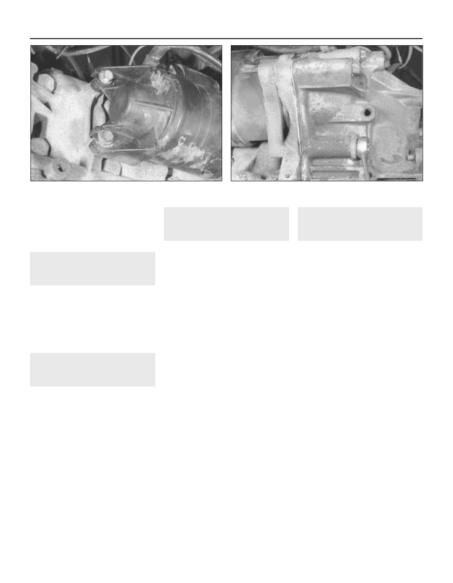
9.5  Starter motor brush end bracket retaining bolts on XV, XW

and XY series engines

9.6  Removing the starter motor mounting bolts on XV, XW 

and XY series engines

5B

Chapter 5  Part B:
Ignition system

System type

All engines except XU5M2/Z, XU5M3/Z, XU5M3/L and TU1M/L . . . . . .

Electronic breakerless ignition system

XU5M2/Z, XU5M3/Z, XU5M3/L and TU1M/L engines  . . . . . . . . . . . . . .

Static distributorless ignition system

Distributor

Rotor arm rotation  . . . . . . . . . . . . . . . . . . . . . . . . . . . . . . . . . . . . . . . . .

Anti-clockwise

Firing order  . . . . . . . . . . . . . . . . . . . . . . . . . . . . . . . . . . . . . . . . . . . . . . .

1 - 3 - 4 - 2 (No 1 cylinder at flywheel end of engine)

Ignition timing (vacuum hose disconnected)

XV8 and XW7 engines  . . . . . . . . . . . . . . . . . . . . . . . . . . . . . . . . . . . . . .

6° BTDC at 650 rpm

XY7 engines  . . . . . . . . . . . . . . . . . . . . . . . . . . . . . . . . . . . . . . . . . . . . . .

8°BTDC at 650 rpm

XY8 engines:

Early models with M152E advance curve . . . . . . . . . . . . . . . . . . . . . .

0° BTDC at 950 rpm

Later models with M159E advance curve . . . . . . . . . . . . . . . . . . . . . .

8° BTDC at 850 to 950 rpm

XU5J engines (up to VIN 5520364) . . . . . . . . . . . . . . . . . . . . . . . . . . . . .

30° BTDC at 3500 rpm or 6° BTDC at 700 rpm

XU5J engines (from VIN 5520364)  . . . . . . . . . . . . . . . . . . . . . . . . . . . . .

10° BTDC at 850 ± 50 rpm

XU5JA and XU5JA/K engines . . . . . . . . . . . . . . . . . . . . . . . . . . . . . . . . .

10° BTDC at 900 rpm

XU51C and XU51C/K engines  . . . . . . . . . . . . . . . . . . . . . . . . . . . . . . . .

10° BTDC at 750 rpm

XU5M2/Z, XU5M3/Z and XU5M3/L engines  . . . . . . . . . . . . . . . . . . . . .

Not adjustable, controlled by MMFD Mono-point G5/6 engine
management system

XU9JA and XU9JA/K engines . . . . . . . . . . . . . . . . . . . . . . . . . . . . . . . . .

5° BTDC at 700 rpm

XU9JA/Z and XU9JA/L engines  . . . . . . . . . . . . . . . . . . . . . . . . . . . . . . .

Not adjustable, controlled by Motronic M1.3 engine management
system

XU9J1/Z and XU9J1/L engines  . . . . . . . . . . . . . . . . . . . . . . . . . . . . . . .

10° BTDC at 900 rpm

TU series engines (except TU1M/L)  . . . . . . . . . . . . . . . . . . . . . . . . . . . .

8° BTDC at idling speed (see Chapter 4)

TU1M/L engines  . . . . . . . . . . . . . . . . . . . . . . . . . . . . . . . . . . . . . . . . . . .

Not adjustable, controlled by MMFD Mono-point G6 engine
management system

Ignition coil

Ignition HT coil resistances:*

Electronic breakerless ignition systems:

Primary windings . . . . . . . . . . . . . . . . . . . . . . . . . . . . . . . . . . . . . . .

0.8 ohms

Secondary windings  . . . . . . . . . . . . . . . . . . . . . . . . . . . . . . . . . . . .

6.5 K ohms

Static distributorless ignition systems:

Primary windings . . . . . . . . . . . . . . . . . . . . . . . . . . . . . . . . . . . . . . .

0.5 to 0.8 ohms

Secondary windings - Bosch coil  . . . . . . . . . . . . . . . . . . . . . . . . . .

14.6 K ohms

Secondary windings - Valeo coil . . . . . . . . . . . . . . . . . . . . . . . . . . .

8.6 K ohms

*The above results are approximate values and are accurate only when the coil is at 20°C. See text for further information
Spark plugs . . . . . . . . . . . . . . . . . . . . . . . . . . . . . . . . . . . . . . . . . . . . . . .

See Chapter 1 Specifications

Distributor (breakerless ignition systems) - removal and refitting  . . . 4
General information  . . . . . . . . . . . . . . . . . . . . . . . . . . . . . . . . . . . . . . 1
Ignition amplifier (breakerless ignition systems) - removal and 

refitting  . . . . . . . . . . . . . . . . . . . . . . . . . . . . . . . . . . . . . . . . . . . . . . 5

Ignition HT coil - removal, testing and refitting  . . . . . . . . . . . . . . . . . 3
Ignition module (static distributorless ignition systems) - removal and

refitting  . . . . . . . . . . . . . . . . . . . . . . . . . . . . . . . . . . . . . . . . . . . . . . 6

Ignition system - testing  . . . . . . . . . . . . . . . . . . . . . . . . . . . . . . . . . . 2
Ignition system check  . . . . . . . . . . . . . . . . . . . . . . . . . . .See Chapter 1
Ignition timing - checking and adjustment  . . . . . . . . . . . . . . . . . . . . 8
Spark plug renewal  . . . . . . . . . . . . . . . . . . . . . . . . . . . . .See Chapter 1
TDC sensor - removal and refitting  . . . . . . . . . . . . . . . . . . . . . . . . . . 9
Timing plate (breakerless ignition systems) - adjustment  . . . . . . . . . 7

5B•1

Specifications

Contents

Easy, suitable for
novice with little
experience

Fairly easy, suitable
for beginner with
some experience

Fairly difficult,
suitable for competent
DIY mechanic

Difficult, suitable for
experienced  DIY
mechanic

Very difficult,
suitable for expert DIY
or  professional

Degrees of difficulty

5

4

3

2

1

1

General information

Electronic breakerless ignition
system

A number of different breakerless ignition

systems are used on 205 models according to
engine type and fuel system fitted. Some are
simple self-contained systems and some
work in conjunction with the fuel system to
form an integrated engine management
package. 

In order that the engine may run correctly it

is necessary for an electrical spark to ignite
the fuel/air mixture in the combustion
chamber at exactly the right moment in
relation to engine speed and load.

Basically the ignition system functions as

follows. Low tension voltage from the battery
is fed to the ignition coil, where it is converted
into high tension voltage. The high tension
voltage is powerful enough to jump the spark
plug gap in the cylinder many times a second
under high compression pressure, providing
that the ignition system is in good working
order.

The distributor contains a reluctor mounted

onto its shaft and a magnet and stator fixed to
its body. An ignition amplifier unit is mounted
either remotely, adjacent to the ignition coil, or
on the side of the distributor body.

When the ignition is switched on but the

engine is stationary the transistors in the
amplifier unit prevent current flowing through
the ignition system primary (LT) circuit.

As the crankshaft rotates, the reluctor

moves through the magnetic field created by
the stator. When the reluctor teeth are in
alignment with the stator projections a small
AC voltage is created. The amplifier unit uses
this voltage to switch the transistors in the
unit and complete the ignition system primary
(LT) circuit.

As the reluctor teeth move out of alignment

with the stator projections the AC voltage
changes and the transistors in the amplifier
unit are switched again to interrupt the
primary (LT) circuit. This causes a high voltage
to be induced in the coil secondary (HT)
windings which then travels down the HT lead
to the distributor and onto the relevant spark
plug.

The ignition is advanced and retarded

automatically by centrifugal weights and a
vacuum capsule or by the engine
management electronic control unit to ensure
that the spark occurs at the correct instant in
relation to engine speed and load.

Static distributorless ignition
system

A static ignition system is used on models

with MMFD Mono-point G5 and G6 engine
management systems. The system is
integrated with the fuel injection system, and is

controlled by the MMFD electronic control unit
(ECU). The ECU receives information from
various sensors, and using this information, the
optimum ignition advance for the prevailing
engine conditions is selected from a series of
“mapped” values stored in the ECU memory
(see Chapter 4B for further information).

The single ignition module replaces the

amplifier unit, HT coil and distributor in a
conventional system. The ignition module
incorporates a double coil, with four
high-tension outputs to the spark plugs,
which dispenses with the requirement for a
conventional distributor and rotor arm.

Each coil is controlled by the MMFD

electronic control unit. Each time one of the
coil primary circuits is switched, two sparks
are provided, one to a cylinder on the
compression stroke, and one to a cylinder on
the exhaust stroke. The spark to the cylinder
on the exhaust stroke is effectively a “wasted
spark”, but has no detrimental effect on the
performance of the engine.

2

Ignition system - testing

2

Warning: Voltages produced by
an electronic ignition system are
considerably higher than those
produced by conventional

ignition systems. Extreme care must be
taken when working on the system with the
ignition switched on. Persons with
surgically-implanted cardiac pacemaker
devices should keep well clear of the ignition
circuits, components and test equipment.

Models with electronic
breakerless ignition systems

Note: Refer to the warning given in Section 1
of Part A of this Chapter before starting work.
Always switch off the ignition before
disconnecting or connecting any component
and when using a multi-meter to check
resistances.

General

The components of electronic ignition
systems are normally very reliable; most faults
are far more likely to be due to loose or dirty
connections or to “tracking” of HT voltage
due to dirt, dampness or damaged insulation
than to the failure of any of the system’s
components.  Always

check all wiring

thoroughly before condemning an electrical
component and work methodically to
eliminate all other possibilities before deciding
that a particular component is faulty.
The old practice of checking for a spark by
holding the live end of an HT lead a short
distance away from the engine is not
recommended; not only is there a high risk of
a powerful electric shock, but the HT coil or
amplifier unit will be damaged. Similarly,
never try to “diagnose” misfires by pulling off
one HT lead at a time.

Engine will not start

If the engine either will not turn over at all,
or only turns very slowly, check the battery
and starter motor. Connect a voltmeter across
the battery terminals (meter positive probe to
battery positive terminal), disconnect the
ignition coil HT lead from the distributor cap
and earth it, then note the voltage reading
obtained while turning over the engine on the
starter for (no more than) ten seconds. If the
reading obtained is less than approximately
9.5 volts, first check the battery, starter motor
and charging system as described in Part A of
this Chapter.
If the engine turns over at normal speed but
will not start, check the HT circuit by
connecting a timing light (following the
manufacturer’s instructions) and turning the
engine over on the starter motor; if the light
flashes, voltage is reaching the spark plugs,
so these should be checked first. If the light
does not flash, check the HT leads
themselves followed by the distributor cap,
carbon brush and rotor arm using the
information given in Chapter 1.
If there is a spark, check the fuel system for
faults referring to the relevant part of Chapter
4 for further information.
If there is still no spark, check the voltage at
the ignition HT coil “+” terminal; it should be
the same as the battery voltage (ie, at least
11.7 volts). If the voltage at the coil is more
than 1 volt less than that at the battery, check
the feed back through the fusebox and
ignition switch to the battery and its earth until
the fault is found.
If the feed to the HT coil is sound, check the
coil’s primary and secondary winding
resistance as described later in this Chapter;
renew the coil if faulty, but be careful to check
carefully the condition of the LT connections
themselves before doing so, to ensure that
the fault is not due to dirty or poorly-fastened
connectors.
If the HT coil is in good condition, the fault
is probably within the amplifier unit or
distributor stator assembly. Testing of these
components should be entrusted to a
Peugeot dealer.

Engine misfires

An irregular misfire suggests either a loose
connection or intermittent fault on the primary
circuit, or an HT fault on the coil side of the
rotor arm.
10 With the ignition switched off, check
carefully through the system ensuring that all
connections are clean and securely fastened.
If the equipment is available, check the LT
circuit as described above.
11 Check that the HT coil, the distributor cap
and the HT leads are clean and dry. Check the
leads themselves and the spark plugs (by
substitution, if necessary), then check the
distributor cap, carbon brush and rotor arm as
described in Chapter 1.
12 Regular misfiring is almost certainly due to
a fault in the distributor cap, HT leads or spark

5B•2 Ignition system

plugs. Use a timing light (paragraph 4 above)
to check whether HT voltage is present at all
leads.
13 If HT voltage is not present on any
particular lead, the fault will be in that lead or
in the distributor cap. If HT is present on all
leads, the fault will be in the spark plugs;
check and renew them if there is any doubt
about their condition.
14 If no HT is present, check the HT coil; its
secondary windings may be breaking down
under load.

Models with static
distributorless ignition systems

15 If a fault appears in the engine
management (fuel injection/ignition) system
first ensure that the fault is not due to a poor
electrical connection or poor maintenance; ie,
check that the air cleaner filter element is
clean, the spark plugs are in good condition
and correctly gapped, that the engine breather
hoses are clear and undamaged, referring to
Chapter 1 for further information. Also check
that the throttle cable is correctly adjusted as
described in the relevant part of Chapter 4. If
the engine is running very roughly, check the
compression pressures and the valve
clearances as described in Chapter 2B or 2C.
16 If these checks fail to reveal the cause of
the problem the vehicle should be taken to a
suitably equipped Peugeot dealer for testing.
A wiring block connector is incorporated in
the engine management circuit into which a
special electronic diagnostic tester can be
plugged. The tester will locate the fault quickly
and simply alleviating the need to test all the
system components individually which is a
time consuming operation that carries a high
risk of damaging the ECU.
17 The only ignition system checks which
can be carried out by the home mechanic are
those described in Chapter 1, relating to the
spark plugs, and the ignition coil test
described in this Chapter. If necessary, the
system wiring and wiring connectors can be
checked as described in Chapter 12 ensuring
that the ECU wiring connector(s) have first
been disconnected.

3

Ignition HT coil - removal,
testing and refitting

2

Note: On models with static distributorless
ignition systems, the ignition HT coil is an
integral part of the ignition module. Refer to
Section 6 for removal and refitting
procedures.

Removal

All engines except TU series

The ignition HT coil is located at the left-
hand side of the engine compartment mounted
on the side of the suspension strut tower.
Disconnect the battery negative lead.

Slide the cover off the coil and adjacent
ignition module (see illustration)
Disconnect the wiring at the coil LT
terminals, and the HT lead at the coil centre
terminal.
Release the coil mounting clamp and
remove the coil. 

TU series engines

The ignition HT coil is mounted on the left-
hand end of the cylinder head, above the
distributor.
Disconnect the battery negative lead.
Refer to the relevant Part of Chapter 4 and
remove the air cleaner assembly. Once the air
cleaner is removed, move aside any pipes,
hoses or wiring as necessary for improved
access.
Where applicable, disconnect the wiring
connector from the capacitor mounted on the
coil mounting bracket and release the TDC
sensor wiring connector from the bracket.
10 Disconnect the HT lead from the coil then
depress the retaining clip and disconnect the
coil wiring connector (see illustration).
11 Slacken and remove the two retaining
bolts and remove the coil and mounting
bracket from the cylinder head. Where
necessary, slacken and remove the four
screws and nuts and separate the HT coil and
mounting bracket.

Testing

12 Testing of the coil consists of using a
multimeter set to its resistance function, to
check the primary (LT “+’“ to “-” terminals) and
secondary (LT “+” to HT lead terminal)
windings for continuity, bearing in mind that on
the four output, static type HT coil there are
two sets of each windings. Compare the
results obtained to those given in the
Specifications at the start of this Chapter. Note
the resistance of the coil windings will vary
slightly according to the coil temperature, the
results in the Specifications are approximate
values for when the coil is at 20°C.
13 Check that there is no continuity between
the HT lead terminal and the coil
body/mounting bracket.
14 If the coil is thought to be faulty, have your
findings confirmed by a Peugeot dealer before
renewing the coil.

Refitting (all models)

15 Refitting is a reversal of the relevant
removal procedure ensuring that the wiring
connectors are securely reconnected and,
where necessary, the HT leads are correctly
connected.

4

Distributor (breakerless
ignition systems) - 
removal
and refitting

2

Removal

All engines except TU series

Disconnect the battery negative lead.
Remove the air cleaner and/or inlet duct, as
necessary for access, with reference to the
relevant Part of Chapter 4.
Identify the HT leads for position then
disconnect them from the spark plugs.
Slide off the ignition coil cover and
disconnect the HT lead from the coil.
Pull back the plastic cover then unclip and
remove the distributor cap (see illustration).
Note that on certain later models the cap is
retained by two screws instead of clips.
Disconnect the wiring at the connector,
where necessary pulling out the spring clip
first.
Pull the hose from the vacuum advance
unit.
Mark the distributor mounting flange in
relation to the cylinder head or thermostat
housing as applicable.

Ignition system  5B•3

5B

3.3  On all engines except TU series,

access to the coil and ignition module is

gained after sliding up the protective cover

3.10  Disconnecting the coil wiring

connector (arrowed) on TU series engines

4.5  Pull back the plastic cover then unclip

and remove the distributor cap

Unscrew the mounting nuts, remove the
small plates, and withdraw the distributor (see
illustrations)
.
10 Check the condition of the O-ring on the
mounting flange and renew it if necessary.

TU series engines

11 Remove the ignition HT coil (Section 3).
12 Identify the HT leads for position, then
disconnect them from the spark plugs.
13 Unbolt the HT lead support from the
cylinder head.
14 Pull back the plastic cover, then extract
the screws and remove the distributor cap.
15 Disconnect the wiring at the connector
(see illustration).
16 Pull the hose from the vacuum advance
unit.
17 Mark the distributor mounting flange in
relation to the distributor/fuel pump housing
(see illustration).
18 Unscrew the mounting nuts, remove the
small plates, and withdraw the distributor (see
illustration)
.
19 Check the condition of the O-ring on the
mounting flange, and renew it if necessary.

Refitting

All engines

20 Refitting is a reversal of removal, but turn
the rotor arm as required to align the lugs with
the offset slot in the camshaft. If the old
distributor is being refitted, align the
previously made marks before tightening the
mounting nuts. If fitting a new distributor,
initially set the distributor in the middle of the

slotted holes or follow the procedure given in
Section 8, then finally adjust the ignition
timing (Section 8).

5

Ignition amplifier (breakerless
ignition systems) - 
removal
and refitting

2

Removal

All engines except TU series

The ignition amplifier unit is located at the
left-hand side of the engine compartment
mounted on the side of the suspension strut
tower.
Disconnect the battery negative lead. 
Slide the cover off the ignition HT coil and
amplifier. 
Disconnect the amplifier wiring harness. 
Remove the screws and withdraw the
amplifier from the mounting plate. 

TU series engines

The amplifier unit is attached to the side of
the distributor.
Disconnect the battery negative lead. 
Disconnect the amplifier wiring at the
connector.
Remove the two screws and withdraw the
amplifier from the distributor, taking care not
to bend the terminals (see illustration).
10 Do not wipe away the special
heat-conductive grease, as this protects the
semi-conductor components within the
amplifier. If necessary, obtain new grease
from a Peugeot dealer.

Refitting

All engines

11 Refitting is a reversal of removal. On TU
series engines, make sure that the special
grease is spread evenly over the mating
surfaces of both the distributor and amplifier
unit.

6

Ignition module (distributorless
ignition systems) - 
removal and
refitting

2

Removal

The ignition module is mounted on the left-
hand end of the cylinder head.
Disconnect the battery negative lead.
Where necessary, remove the air cleaner
ducting for improved access.

5B•4 Ignition system

4.9a  On non-TU series engines, unscrew

the mounting nuts . . .

4.9b  . . . and remove the distributor

4.15  Disconnect the distributor wiring

connector on TU series engines

4.17  Mark the distributor and housing . . .

4.18  . . . then remove the distributor

6.5  HT lead connections on the static

distributorless ignition module

5.9  Removing the ignition amplifier on TU

series engines

Depress the retaining clip and disconnect
the wiring connector from the module.
Make a note of the correct fitted positions
of the HT leads then disconnect them from
the module terminals (see illustration).
Undo the four retaining screws securing the
module to its mounting bracket and remove it
from the engine.

Refitting

Refitting is a reversal of removal.

7

Timing plate (breakerless
ignition systems) 
-
adjustment

2

Note: Timing plate adjustment is only possible
on models fitted with XV, XW and XY series
engines. Peugeot special tool 80133 or a
suitable alternative will be required for the
adjustment procedure
.
The timing plate which is located in the
aperture under the plastic cover at the top of
the flywheel housing can be moved within the
limits of its elongated slot (see illustration)
The plate is set during production and
should not be disturbed unless a new
flywheel, flywheel housing or other associated
components have been fitted.
To adjust the timing plate, carry out the
following operations.
Remove the plastic cover.
Using the crankshaft pulley nut, turn the
crankshaft until the mark on the flywheel is at
the start of the timing plate.
Remove the plug from behind the
crankshaft pulley using an Allen key. Note that
if the hole in the pulley is not over the plug, the
crankshaft should be turned exactly half a
turn. This is because there are two
diametrically opposite timing marks on the
flywheel, and the mark corresponding to TDC
on No 2 and 3 cylinders must be used to bring
the slot in the crankshaft counterbalance in
line with the plug hole.
Insert the crankshaft locking tool (Peugeot
special tool 80133) into the plug hole and turn
the crankshaft until the tool is felt to drop into
the cut-out in the counterbalance weight of
the crankshaft.

If the special tool is not available, a suitable
alternative can be used (see Tool Tip).
With the tool or dowel rod inserted, pistons
2 and 3 are now located at TDC.
10 Release the timing plate bolt and move
the plate to align the flywheel, and 0 (TDC)
mark on the plate. Tighten the bolt to the
specified torque. Apply a blob of paint on the
edge of the bolt so that any subsequent
movement can be recognised.
11 Withdraw the tool, fit a new sealing ring to
the plug and tighten securely.

8

Ignition timing - checking and
adjustment

2

Note: On engines equipped with MMFD
Mono-point G5/6 or Motronic M1.3 engine
management systems the ignition timing is
controlled by the system ECU and cannot be
adjusted.

XV, XW and XY series engines

To set the ignition timing statically so that
the engine can be started first remove No 2
spark plug and turn the engine in the normal
rotational direction until pressure is felt -
indicating that the piston is commencing the
compression stroke. The pressure can be felt
using a suitable wooden rod or a piece of cork
placed over the spark plug hole.
Remove the plastic cover from the timing
aperture then continue turning the crankshaft

until the mark on the flywheel is opposite the
BTDC mark on the timing plate (see
illustration)
.
Check that the distributor rotor arm is
facing the No 2 HT lead segment position in
the distributor cap. To do this, remove the cap
and mark the outside in line with the segment,
then put it back on the distributor noting
which way the rotor arm is facing.
If necessary, loosen the mounting nuts and
turn the distributor body to bring the segment
and rotor arm in line, then tighten the nuts.
Refit No 2 spark plug.
Run the engine to normal operating
temperature then stop it and connect a
tachometer and stroboscopic timing light as
described in the instrument manufacturer’s
instructions. If the HT pick-up lead of the
timing light is connected to the HT lead on the
ignition coil it is possible to detect any
discrepancy between the firing of Nos 1 and 4
and Nos 2 and 3 cylinders since there are two
diametrically opposite timing marks on the
flywheel. However, the pick-up lead may be
connected to any one of the spark plug HT
leads, in which case only one of the flywheel
timing marks will be used.
Disconnect and plug the vacuum pipe at
the distributor vacuum advance unit.
Run the engine at the specified speed and
point the timing light into the timing aperture.
The single mark on the flywheel should be
aligned with the BTDC mark on the timing
plate (see illustration). If the ignition coil HT
lead has been used (see paragraph 5), and
there is wear in the distributor, there will be
two marks visible on the flywheel close to
each other. In this case the mid-point
between the two marks should be aligned
with the BTDC mark on the timing plate.
If adjustment is necessary, loosen the
distributor mounting nuts and rotate the
distributor body as required. Tighten the nuts
on completion. 
The operation of the centrifugal advance
weights in the distributor can be checked by
increasing the engine speed with the timing
light pointing in the timing aperture and
observing that the mark on the flywheel
advances from its initial position.

Ignition system  5B•5

5B

7.1  Timing plate components on XV, XW

and XY series engines

1 Diagnostic socket
2 Cover

3 Timing plate

8.2  Timing plate marks on XV, XW and XY

series engines

8.7  Ignition timing adjustment on XV, XW

and XY series engines

A Using spark plug HT lead
B Using ignition coil HT lead

A crankshaft locking tool can be made
from a 100 mm length of 8.0 mm dowel
rod.

10 To check the vacuum advance unit, run
the engine at a fast idle speed and reconnect
the vacuum pipe. The flywheel mark should
again advance.
11 Stop the engine, disconnect the
tachometer and timing light and reconnect the
vacuum pipe. Refit the timing aperture cover.

XU series engines

12 To set the ignition timing statically so that
the engine can be started, first remove No 1
spark plug (nearest the flywheel) and turn the
engine in the normal rotational direction until
pressure is felt - indicating that the piston is
commencing the compression stroke. The
pressure can be felt using a suitable wooden
rod or piece of cork placed over the spark
plug hole.
13 While looking into the timing aperture in
the clutch housing/transmission casing,
continue turning the crankshaft until the single
mark on the flywheel is opposite the BTDC
mark on the timing plate (see illustration).
14 Check that the distributor rotor arm is
facing the No 1 HT lead segment position in
the distributor cap. To do this, remove the cap
and mark the outside in line with the segment,
then put it back on the distributor noting
which way the rotor arm is facing.
15 If necessary, loosen the mounting nuts
and turn the distributor body to bring the
segment and rotor arm in line, then tighten the
nuts. Refit No 1 spark plug.
16 Run the engine to normal operating
temperature then stop it and connect a
tachometer to it.
17 Disconnect and plug the vacuum pipe at
the distributor vacuum advance unit.
18 Disconnect and remove the air cleaner
inlet duct then connect a stroboscopic timing
light to the engine as described in the timing

light manufacturer’s instructions, and with the
HT pick-up lead connected to No 1 spark plug
HT lead.
19 On early models, run the engine at 3500
rpm and point the timing light into the timing
aperture. The double mark on the flywheel
should be aligned with the TDC mark on the
timing plate; indicating that the ignition is
advanced by 30° (see illustration). On
engines without double timing marks, refer to
the  Specifications for the relevant ignition
timing setting and engine speed, then check
that the single mark on the flywheel is aligned
with the appropriate mark on the timing plate.
20 If adjustment is necessary, loosen the
distributor mounting nuts and rotate the
distributor body as required. Tighten the nuts
on completion. 
21 Check the centrifugal and vacuum
advance characteristics of the distributor, as
described in paragraphs 9 and 10.
22 Stop the engine, disconnect the
tachometer and timing light then reconnect
the vacuum pipe and air cleaner inlet duct.

TU series engines

23 To set the ignition timing statically so that
the engine can be started, refer to the
procedures contained in paragraphs 12 to 15
above.
24 To check the ignition timing, a
stroboscopic timing light will be required. It is
also recommended that the flywheel timing
mark is highlighted as follows.
25 Remove the plug from the aperture on the
front of the transmission clutch housing.
Using a socket and suitable extension bar on
the crankshaft pulley bolt, slowly turn the
engine over until the timing mark (a straight
line) scribed on the edge of the flywheel
appears in the aperture. Highlight the line with
quick-drying white paint - typist’s correction
fluid is ideal (see illustrations).
26 Start the engine, allow it to warm up to
normal operating temperature, and then stop
it.
27 Disconnect the vacuum hose from the
distributor diaphragm, and plug the hose end.

5B•6 Ignition system

8.25a  On TU series engines, remove the

plug from the transmission housing . . .

8.25b  . . . to reveal the timing plate and

flywheel timing mark (arrowed)

8.13  Initial static ignition timing on XU series engines

a Single flywheel mark

b BTDC mark on timing plate

8.19  Dynamic ignition timing on XU series engines

a Double flywheel mark

b TDC mark on timing plate

28 Connect the timing light to No 1 cylinder
spark plug lead (No 1 cylinder is at the
transmission end of the engine) as described
in the timing light manufacturer’s instructions.
29 Start the engine, allowing it to idle at the
specified speed, and point the timing light at
the transmission housing aperture. The
flywheel timing mark should be aligned with
the appropriate notch on the timing plate. The
numbers on the plate indicate degrees Before
Top Dead Centre (BTDC).
30 If adjustment is necessary, slacken the
two distributor mounting nuts, then slowly
rotate the distributor body as required until
the flywheel mark and the timing plate notch
are brought into alignment. Once the marks
are correctly aligned, hold the distributor
stationary and tighten its mounting nuts.
Recheck that the timing marks are still
correctly aligned and, if necessary, repeat the
adjustment procedure.
31 When the timing is correctly set, increase
the engine speed, and check that the flywheel
mark advances to beyond the beginning of
the timing plate reference marks, returning to
the specified mark when the engine is allowed
to idle. This shows that the centrifugal

advance mechanism is functioning.
Reconnect the vacuum hose to the
distributor, and repeat the check. The rate of
advance should significantly increase if the
vacuum diaphragm is functioning correctly.
32 When the ignition timing is correct, stop
the engine and disconnect the timing light.

9

TDC sensor - removal and
refitting

2

Removal

Depending on engine type, the TDC sensor
is for use with the diagnostic socket located
on the clutch housing, or for the provision of
information on crankshaft position to the
engine management system ECU. When used
in conjunction with the diagnostic socket, a
special instrument and adapter are required
and therefore it will normally be used only by a
Peugeot garage.
To remove the sensor, unscrew the
mounting screw or release the clamp as
applicable.

Where the sensor forms part of the
diagnostic socket assembly, if it is to be
completely removed, the socket must be
unclipped from its bracket and the remaining
wiring and earth leads disconnected.

Refitting

Refitting is a reversal of removal, but the
adjustment procedure for new and used
sensors differs. New sensors have three
extensions on the inner face and the unit
should be inserted through the clamp until the
extensions just touch the flywheel. The clamp
screw is then tightened and clearance is
provided as the flywheel rotates and wears
the ends of the extensions. This method
should not be used when refitting a used
sensor. In this case, cut off the extensions
completely then temporarily insert the sensor
until it touches the flywheel, remove it and
reposition it in the clamp 1.0 mm further out.

Ignition system  5B•7

5B


Content   ..  16  17  18  19   ..