Peugeot 205 (954 cc, 1124 cc, 1360 cc, 1580 cc & 1905 cc). Manual - part 8


  Index      Manuals     Peugeot 205 Haynes (954 cc, 1124 cc, 1360 cc, 1580 cc & 1905 cc). Repair Manual


Search            


Content   ..  6  7  8  9   ..


Peugeot 205 (954 cc, 1124 cc, 1360 cc, 1580 cc & 1905 cc). Manual - part 8


Refitting

15 Refitting is a reversal of removal, but
tighten the union nuts carefully to the
specified torque while holding the connection
stubs stationary. Check and if necessary top-
up the engine oil as described in “Weekly
checks”.

12 Crankshaft oil seals -

renewal

4

Right-hand oil seal

Remove the crankshaft sprocket and,
where fitted, the spacer as described in
Section 5.
Punch or drill two small holes opposite each
other in the seal. Screw a self-tapping screw
into each, and pull on the screws with pliers to
extract the seal. Alternatively, the seal can be
levered out of position. Use a flat-bladed
screwdriver, and take great care not to damage
the crankshaft shoulder or seal housing.
Clean the seal housing, and polish off any
burrs or raised edges, which may have
caused the seal to fail in the first place.
Lubricate the lips of the new seal with clean
engine oil, and carefully locate the seal on the
end of crankshaft. Note that its sealing lip
must be facing inwards. Take care not to
damage the seal lips during fitting.
Fit the new seal using a suitable tubular
drift, such as a socket, which bears only on
the hard outer edge of the seal. Tap the seal
into position, to the same depth in the housing
as the original was prior to removal.
Wash off any traces of oil, then refit the
crankshaft sprocket as described in Section 5.

Left-hand oil seal

Remove the flywheel/driveplate as
described in Section 13. Make a note of the
correct fitted depth of the seal in its housing.
Punch or drill two small holes opposite
each other in the seal. Screw a self-tapping
screw into each, and pull on the screws with
pliers to extract the seal.
Clean the seal housing, and polish off any
burrs or raised edges, which may have
caused the seal to fail in the first place.

10 Lubricate the lips of the new seal with
clean engine oil, and carefully locate the seal
on the end of the crankshaft.
11 Fit the new seal using a suitable tubular
drift, which bears only on the hard outer edge
of the seal. Drive the seal into position, to the
same depth in the housing as the original was
prior to removal.
12 Wash off any traces of oil, then refit the
flywheel/driveplate as described in Section 13.

13 Flywheel/driveplate -

removal, inspection and
refitting

4

Removal

Flywheel (models with manual
transmission)

Remove the transmission as described in
Chapter 7A, then remove the clutch assembly
as described in Chapter 6.
Prevent the flywheel from turning by locking
the ring gear teeth with a screwdriver or
similar tool.
Slacken and remove the flywheel retaining
bolts, and remove the flywheel from the end
of the crankshaft. Be careful not to drop it; it is
heavy. If the flywheel locating dowel is a loose
fit in the crankshaft end, remove it and store it
with the flywheel for safe-keeping. Discard the
flywheel bolts; new ones must be used on
refitting.

Driveplate (models with automatic
transmission)

Remove the transmission as described in
Chapter 7B. Lock the driveplate as described
in paragraph 2. Mark the relationship between
the torque converter plate and the driveplate,
and slacken all the driveplate retaining bolts.
Remove the retaining bolts, along with the
torque converter plate and the two shims
(where fitted). Note that the shims are of
different thickness, the thicker one being on
the outside of the torque converter plate.
Discard the driveplate retaining bolts; new
ones must be used on refitting.
Remove the driveplate from the end of the
crankshaft. If the locating dowel is a loose fit
in the crankshaft end, remove it and store it
with the driveplate for safe-keeping.

Inspection

On models with manual transmission,
examine the flywheel for scoring of the clutch
face, and for wear or chipping of the ring gear
teeth. If the clutch face is scored, the flywheel
may be surface-ground, but renewal is
preferable. Seek the advice of a Peugeot
dealer or engine reconditioning specialist to
see if machining is possible. If the ring gear is
worn or damaged, the flywheel must be
renewed, as it is not possible to renew the
ring gear separately.
On models with automatic transmission,
check the torque converter driveplate

carefully for signs of distortion. Look for any
hairline cracks around the bolt holes or
radiating outwards from the centre, and
inspect the ring gear teeth for signs of wear or
chipping. If any sign of wear or damage is
found, the driveplate must be renewed.

Refitting

Flywheel - models with manual
transmission

Clean the mating surfaces of the flywheel
and crankshaft. Remove any remaining
locking compound from the threads of the
crankshaft holes, using the correct-size tap, if
available.
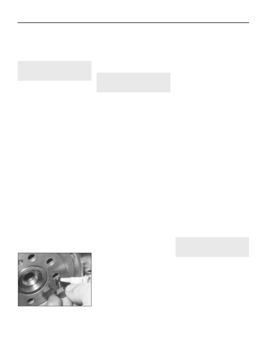
10 If the new flywheel retaining bolts are not
supplied with their threads already pre-
coated, apply a suitable thread-locking
compound to the threads of each bolt (see
illustration)
.
11 Ensure that the locating dowel is in
position. Offer up the flywheel, locating it on
the dowel, and fit the new retaining bolts.
12 Lock the flywheel using the method
employed on dismantling, and tighten the
retaining bolts to the specified torque.
13 Refit the clutch as described in Chapter 6,
and refit the transmission as described in
Chapter 7A.

Driveplate - models with automatic
transmission

14 Carry out the operations described above
in paragraphs 9 and 10, substituting
“driveplate” for all references to the flywheel.
15 Locate the driveplate on its locating
dowel.
16 Offer up the torque converter plate, with
the thinner shim positioned behind the plate
and the thicker shim on the outside, and align
the marks made prior to removal.
17 Fit the new retaining bolts, then lock the
driveplate using the method employed on
dismantling. Tighten the retaining bolts to the
specified torque wrench setting.
18 Refit the transmission as described in
Chapter 7B.

14 Engine/transmission

mountings - inspection and
renewal

3

Refer to Part A, Section 10 but note that on

early models, shims are fitted between the
right-hand mounting rubber buffers and the
mounting top plate. These should be added or
removed as necessary to provide a clearance
of 1.0 mm between the buffers and top plate.
On later models, the shims have been deleted
and the rubber buffers are increased in
thickness to compensate. To prevent scuffing
noises from the buffers, it is recommended
that the inner surfaces which contact the
engine bracket are lubricated with rubber
grease.

2B•12 XU series engine in-car repair procedures

13.10  Apply thread locking compound to

the flywheel bolts if not already pre-coated

2C

Chapter 2  Part C:
TU series engine in-car repair procedures

Engine general

Code and displacement:

TU9  . . . . . . . . . . . . . . . . . . . . . . . . . . . . . . . . . . . . . . . . . . . . . . . . . . .

954 cc

TU1  . . . . . . . . . . . . . . . . . . . . . . . . . . . . . . . . . . . . . . . . . . . . . . . . . . .

1124 cc

TU1M/L  . . . . . . . . . . . . . . . . . . . . . . . . . . . . . . . . . . . . . . . . . . . . . . . .

1124 cc

TU1M/Z  . . . . . . . . . . . . . . . . . . . . . . . . . . . . . . . . . . . . . . . . . . . . . . . .

1124 cc

TU3  . . . . . . . . . . . . . . . . . . . . . . . . . . . . . . . . . . . . . . . . . . . . . . . . . . .

1360 cc

TU3A  . . . . . . . . . . . . . . . . . . . . . . . . . . . . . . . . . . . . . . . . . . . . . . . . . .

1360 cc

TU3A/K  . . . . . . . . . . . . . . . . . . . . . . . . . . . . . . . . . . . . . . . . . . . . . . . .

1360 cc

TU3M/Z  . . . . . . . . . . . . . . . . . . . . . . . . . . . . . . . . . . . . . . . . . . . . . . . .

1360 cc

TU3FM/L  . . . . . . . . . . . . . . . . . . . . . . . . . . . . . . . . . . . . . . . . . . . . . . .

1360 cc

TU3S  . . . . . . . . . . . . . . . . . . . . . . . . . . . . . . . . . . . . . . . . . . . . . . . . . .

1360 cc

TU3S/K  . . . . . . . . . . . . . . . . . . . . . . . . . . . . . . . . . . . . . . . . . . . . . . . .

1360 cc

Bore:

TU9 series  . . . . . . . . . . . . . . . . . . . . . . . . . . . . . . . . . . . . . . . . . . . . . .

70.0 mm

TU1 series  . . . . . . . . . . . . . . . . . . . . . . . . . . . . . . . . . . . . . . . . . . . . . .

72.0 mm

TU3 series  . . . . . . . . . . . . . . . . . . . . . . . . . . . . . . . . . . . . . . . . . . . . . .

75.0 mm

Stroke:

TU9 series  . . . . . . . . . . . . . . . . . . . . . . . . . . . . . . . . . . . . . . . . . . . . . .

62.0 mm

TU1 series  . . . . . . . . . . . . . . . . . . . . . . . . . . . . . . . . . . . . . . . . . . . . . .

69.0 mm

TU3 series  . . . . . . . . . . . . . . . . . . . . . . . . . . . . . . . . . . . . . . . . . . . . . .

77.0 mm

Compression ratio:

TU9 and TU1 series  . . . . . . . . . . . . . . . . . . . . . . . . . . . . . . . . . . . . . .

9.4 : 1

TU3 series  . . . . . . . . . . . . . . . . . . . . . . . . . . . . . . . . . . . . . . . . . . . . . .

9.3 : 1

Direction of crankshaft rotation  . . . . . . . . . . . . . . . . . . . . . . . . . . . . . . .

Clockwise (viewed from right-hand side of vehicle)

Firing order  . . . . . . . . . . . . . . . . . . . . . . . . . . . . . . . . . . . . . . . . . . . . . . .

1-3-4-2 (No 1 cylinder at flywheel end of engine)

Valve clearances (engine cold)

Inlet  . . . . . . . . . . . . . . . . . . . . . . . . . . . . . . . . . . . . . . . . . . . . . . . . . . . .

0.15 to 0.25 mm

Exhaust  . . . . . . . . . . . . . . . . . . . . . . . . . . . . . . . . . . . . . . . . . . . . . . . . . .

0.35 to 0.45 mm

Lubrication system

Oil pump type  . . . . . . . . . . . . . . . . . . . . . . . . . . . . . . . . . . . . . . . . . . . . .

Gear-type, chain-driven off the crankshaft

Minimum oil pressure at 90°C  . . . . . . . . . . . . . . . . . . . . . . . . . . . . . . . .

4 bars at 4000 rpm

Oil pressure warning switch operating pressure  . . . . . . . . . . . . . . . . . .

0.8 bars

Auxiliary drivebelt check and renewal  . . . . . . . . . . . . . . .See Chapter 1
Camshaft and rocker arms - removal, inspection and refitting  . . . . . 10
Camshaft oil seal - renewal  . . . . . . . . . . . . . . . . . . . . . . . . . . . . . . . . 9
Compression test - description and interpretation  . . . . . . . . . . . . . . 2
Crankshaft oil seals - renewal  . . . . . . . . . . . . . . . . . . . . . . . . . . . . . . 14
Cylinder head - removal and refitting  . . . . . . . . . . . . . . . . . . . . . . . . 11
Cylinder head cover - removal and refitting  . . . . . . . . . . . . . . . . . . . 4
Engine assembly/valve timing holes - general information 

and usage  . . . . . . . . . . . . . . . . . . . . . . . . . . . . . . . . . . . . . . . . . . . 3

Engine oil and filter renewal . . . . . . . . . . . . . . . . . . . . . . .See Chapter 1
Engine oil level check  . . . . . . . . . . . . . . . . . . . . . .See “Weekly checks”

Engine/transmission mountings - inspection and renewal  . . . . . . . . 16
Flywheel - removal, inspection and refitting  . . . . . . . . . . . . . . . . . . . 15
General information  . . . . . . . . . . . . . . . . . . . . . . . . . . . . . . . . . . . . . . 1
Oil pump - removal, inspection and refitting  . . . . . . . . . . . . . . . . . . . 13
Sump - removal and refitting  . . . . . . . . . . . . . . . . . . . . . . . . . . . . . . . 12
Timing belt - general information, removal and refitting  . . . . . . . . . . 7
Timing belt covers - removal and refitting  . . . . . . . . . . . . . . . . . . . . . 6
Timing belt tensioner and sprockets - removal, inspection 

and refitting  . . . . . . . . . . . . . . . . . . . . . . . . . . . . . . . . . . . . . . . . . . 8

Valve clearances - checking and adjustment  . . . . . . . . . . . . . . . . . . 5

2C•1

Specifications

Contents

Easy, suitable for
novice with little
experience

Fairly easy, suitable
for beginner with
some experience

Fairly difficult,
suitable for competent
DIY mechanic

Difficult, suitable for
experienced  DIY
mechanic

Very difficult,
suitable for expert DIY
or  professional

Degrees of difficulty

5

4

3

2

1

Torque wrench settings

Nm

lbf ft

Camshaft sprocket retaining bolt  . . . . . . . . . . . . . . . . . . . . . . . . . . . . . .

80

59

Camshaft thrust fork retaining bolt  . . . . . . . . . . . . . . . . . . . . . . . . . . . . .

16

12

Crankshaft pulley retaining bolts  . . . . . . . . . . . . . . . . . . . . . . . . . . . . . .

8

6

Crankshaft sprocket retaining bolt  . . . . . . . . . . . . . . . . . . . . . . . . . . . . .

110

81

Cylinder head bolts (aluminium block engine):

Stage 1  . . . . . . . . . . . . . . . . . . . . . . . . . . . . . . . . . . . . . . . . . . . . . . . .

20

15

Stage 2  . . . . . . . . . . . . . . . . . . . . . . . . . . . . . . . . . . . . . . . . . . . . . . . .

Tighten through a further 240°

Cylinder head bolts (cast-iron block engine):

Stage 1  . . . . . . . . . . . . . . . . . . . . . . . . . . . . . . . . . . . . . . . . . . . . . . . .

20

15

Stage 2  . . . . . . . . . . . . . . . . . . . . . . . . . . . . . . . . . . . . . . . . . . . . . . . .

Tighten through a further 120°

Stage 3  . . . . . . . . . . . . . . . . . . . . . . . . . . . . . . . . . . . . . . . . . . . . . . . .

Tighten through a further 120°

Cylinder head cover nuts  . . . . . . . . . . . . . . . . . . . . . . . . . . . . . . . . . . . .

16

12

Flywheel retaining nuts and bolts  . . . . . . . . . . . . . . . . . . . . . . . . . . . . . .

65

48

Engine-to-transmission bolts  . . . . . . . . . . . . . . . . . . . . . . . . . . . . . . . . .

35

26

Engine/transmission left-hand mounting:

Mounting bracket-to-transmission nuts  . . . . . . . . . . . . . . . . . . . . . . .

20

15

Mounting bracket-to-body bolts . . . . . . . . . . . . . . . . . . . . . . . . . . . . .

25

18

Mounting rubber nuts  . . . . . . . . . . . . . . . . . . . . . . . . . . . . . . . . . . . . .

20

15

Centre nut  . . . . . . . . . . . . . . . . . . . . . . . . . . . . . . . . . . . . . . . . . . . . . .

65

48

Engine/transmission rear mounting:

Mounting-to-cylinder block bolts  . . . . . . . . . . . . . . . . . . . . . . . . . . . .

40

30

Mounting link-to-mounting bolt  . . . . . . . . . . . . . . . . . . . . . . . . . . . . .

70

52

Mounting link-to-body bolt  . . . . . . . . . . . . . . . . . . . . . . . . . . . . . . . . .

50

37

Engine/transmission right-hand mounting bracket nuts  . . . . . . . . . . . .

45

33

Oil pump retaining bolts  . . . . . . . . . . . . . . . . . . . . . . . . . . . . . . . . . . . . .

8

6

Sump retaining nuts and bolts  . . . . . . . . . . . . . . . . . . . . . . . . . . . . . . . .

8

6

Timing belt cover bolts  . . . . . . . . . . . . . . . . . . . . . . . . . . . . . . . . . . . . . .

8

6

Timing belt tensioner pulley nut  . . . . . . . . . . . . . . . . . . . . . . . . . . . . . . .

23

17

1

General information

How to use this Chapter

This Part of Chapter 2 describes those

repair procedures that can reasonably be
carried out on the TU series engine while it
remains in the car. If the engine has been
removed from the car and is being dismantled
as described in Part D, any preliminary
dismantling procedures can be ignored. Refer
to Part A and B for information on the XV, XW
and XY series and XU series engines.

Part D describes the removal of the

engine/transmission from the vehicle, and the
full overhaul procedures that can then be
carried out.

Engine description

The engine is of the in-line four-cylinder,

overhead camshaft type, mounted
transversely at the front of the car and inclined
forward by 6°. The clutch and transmission
are attached to its left-hand end. The 205
range is fitted with 954 cc (TU9), 1124 cc
(TU1), and 1360 cc (TU3) versions of the
engine in either carburettor or fuel-injected
configuration.

The crankshaft runs in five main bearings.

Thrustwashers are fitted to No 2 main bearing
(upper half) to control crankshaft endfloat.

The connecting rods rotate on horizontally-

split bearing shells at their big-ends. The

pistons are attached to the connecting rods
by gudgeon pins, which are an interference fit
in the connecting rod small-end eyes. The
aluminium-alloy pistons are fitted with three
piston rings - two compression rings and an
oil control ring.

On all except TU3FM engines, the cylinder

block is made of aluminium, and replaceable
wet liners are fitted to the cylinder bores.
Sealing O-rings are fitted at the base of each
liner, to prevent the escape of coolant into the
sump.

On TU3FM engines, the cylinder block is

made from cast-iron, and the cylinder bores
are an integral part of the cylinder block. On
this type of engine, the cylinder bores are
sometimes referred to as having dry liners.

The inlet and exhaust valves are each

closed by coil springs, and operate in guides
pressed into the cylinder head; the valve seat
inserts are also pressed into the cylinder
head, and can be renewed separately if worn.

The camshaft is driven by a toothed timing

belt, and operates the eight valves via rocker
arms. Valve clearances are adjusted by a
screw-and-locknut arrangement. The
camshaft rotates directly in the cylinder head.
The timing belt also drives the coolant pump.

Lubrication is by means of an oil pump,

which is driven (via a chain and sprocket) off
the right-hand end of the crankshaft. It draws
oil through a strainer located in the sump, and
then forces it through an externally-mounted
filter into galleries in the cylinder
block/crankcase. From there, the oil is

distributed to the crankshaft (main bearings)
and camshaft. The big-end bearings are
supplied with oil via internal drillings in the
crankshaft, while the camshaft bearings also
receive a pressurised supply. The camshaft
lobes and valves are lubricated by splash, as
are all other engine components.

Repair operations possible with
the engine in the car

The following work can be carried out with

the engine in the car:

a) Compression pressure - testing.
b) Cylinder head cover - removal and

refitting.

c) Valve clearances - adjustment.
d) Timing belt covers - removal and refitting 
e) Timing belt - removal, refitting and

adjustment.

f) Timing belt tensioner and sprockets -

removal, inspection and refitting.

g) Camshaft oil seal - renewal.
h) Camshaft and rocker arms - removal,

inspection and refitting.

i) Cylinder head - removal and refitting. 
j) Cylinder head and pistons -

decarbonising.

k) Sump - removal and refitting.
l) Oil pump - removal, inspection and

refitting.

m) Crankshaft oil seals - renewal.
n) Flywheel - removal, inspection and

refitting.

o) Engine/transmission mountings -

inspection and renewal.

2C•2 TU series engine in-car repair procedures

2

Compression test -
description and interpretation

Refer to Part A, Section 3 but on engines

with a static distributorless ignition system,
disable the ignition by depressing the
retaining clip and disconnecting the wiring
connector from the ignition module. 

3

Engine assembly/valve
timing holes - 
general
information and usage

Note: Do not attempt to rotate the engine
whilst the crankshaft/camshaft are locked in
position. If the engine is to be left in this state
for a long period of time, it is a good idea to
place warning notices inside the vehicle, and
in the engine compartment. This will reduce
the possibility of the engine being accidentally
cranked on the starter motor, which is likely to
cause damage with the locking pins in place.
On all models, timing holes are drilled in the
camshaft sprocket and in the rear of the
flywheel. The holes are used to ensure that the
crankshaft and camshaft are correctly
positioned when assembling the engine (to

prevent the valves contacting the pistons when
refitting the cylinder head), or refitting the
timing belt. When the timing holes are aligned
with access holes in the cylinder head and the
front of the cylinder block, suitable diameter
pins can be inserted to lock both the camshaft
and crankshaft in position, preventing them
from rotating. Proceed as follows.
Remove the timing belt upper cover as
described in Section 6.
The crankshaft must now be turned until
the timing hole in the camshaft sprocket is
aligned with the corresponding hole in the
cylinder head. The holes are aligned when the
camshaft sprocket hole is in the 2 o’clock
position, when viewed from the right-hand
end of the engine. The crankshaft can be
turned by using a spanner on the crankshaft
sprocket bolt, noting that it should always be
rotated in a clockwise direction (viewed from
the right-hand end of the engine).
With the camshaft sprocket hole correctly
positioned, insert a 6 mm diameter bolt or drill
through the hole in the front, left-hand flange of
the cylinder block, and locate it in the timing
hole in the rear of the flywheel (see illustration).
Note that it may be necessary to rotate the
crankshaft slightly, to get the holes to align.
With the flywheel correctly positioned,
insert a 10 mm diameter bolt or a drill through

the timing hole in the camshaft sprocket, and
locate it in the hole in the cylinder head (see
illustration)
.
The crankshaft and camshaft are now
locked in position, preventing unnecessary
rotation.

4

Cylinder head cover -
removal and refitting

2

Removal

Disconnect the battery negative lead.
Where necessary, undo the bolts securing
the HT lead retaining clips to the rear of the
cylinder head cover, and position the clips
clear of the cover.
Slacken the retaining clip, and disconnect
the breather hose from the left-hand end of
the cylinder head cover (see illustration).
Where the original crimped-type Peugeot
hose clip is still fitted, cut it off and discard it.
Use a standard worm-drive clip on refitting.
Undo the two retaining nuts, and remove
the washer from each of the cylinder head
cover studs (see illustration).
Lift off the cylinder head cover, and remove
it along with its rubber seal (see illustration).

TU series engine in-car repair procedures  2C•3

2C

4.3  Disconnect the breather hose from the

cylinder head cover . . .

4.4  . . . then slacken and remove the cover

retaining nuts and washers (arrowed) . . .

4.5  . . . and lift off the cylinder head cover

3.4  Insert a 6 mm bolt (arrowed) through hole in cylinder block

flange and into timing hole in flywheel . . .

3.5  . . .  then insert a 10 mm bolt through the camshaft sprocket

timing hole, and locate it in the cylinder head

Examine the seal for signs of damage and
deterioration, and if necessary, renew it.
Remove the spacer from each stud, and lift
off the oil baffle plate (see illustrations).

Refitting

Carefully clean the cylinder head and cover
mating surfaces, and remove all traces of oil.
Fit the rubber seal over the edge of the
cylinder head cover, ensuring that it is
correctly located along its entire length (see
illustration)
.
Refit the oil baffle plate to the engine, and
locate the spacers in their recesses in the
baffle plate.
10 Carefully refit the cylinder head cover to
the engine, taking great care not to displace
the rubber seal.
11 Check that the seal is correctly located,
then refit the washers and cover retaining
nuts, and tighten them to the specified torque.
12 Where necessary, refit the HT lead clips to
the rear of the head cover, and securely
tighten their retaining bolts.
13 Reconnect the breather hose to the
cylinder head cover, securely tightening its
retaining clip, and reconnect the battery
negative lead.

5

Valve clearances - checking
and adjustment

2

Note: The valve clearances must be checked
and adjusted only when the engine is cold.

The importance of having the valve
clearances correctly adjusted cannot be
overstressed, as they vitally affect the
performance of the engine. If the clearances are
too big, the engine will be noisy (characteristic
rattling or tapping noises) and engine efficiency
will be reduced, as the valves open too late and
close too early. A more serious problem arises if
the clearances are too small, however. If this is
the case, the valves may not close fully when
the engine is hot, resulting in serious damage to
the engine (eg. burnt valve seats and/or cylinder
head warping/cracking). The clearances are
checked and adjusted as follows.
Remove the cylinder head cover as
described in Section 4.
The engine can now be turned using a
suitable socket and extension bar fitted to the
crankshaft sprocket/pulley bolt.

It is important that the clearance of each
valve is checked and adjusted only when the
valve is fully closed, with the rocker arm
resting on the heel of the cam (directly
opposite the peak). This can be ensured by
carrying out the adjustments in the following
sequence, noting that No 1 cylinder is at the
transmission end of the engine. The correct
valve clearances are given in the
Specifications at the start of this Chapter. The
valve locations can be determined from the
position of the manifolds.

Valve fully open

Adjust valves

No 1 exhaust

No 3 inlet, No 4 exhaust

No 3 exhaust

No 4 inlet, No 2 exhaust

No 4 exhaust

No 2 inlet, No 1 exhaust

No 2 exhaust

No 1 inlet, No 3 exhaust

With the relevant valve fully open, check the
clearances of the two valves specified. The
clearances are checked by inserting a feeler
blade of the correct thickness between the
valve stem and the rocker arm adjusting screw
(see illustration). The feeler blade should be a
light, sliding fit. If adjustment is necessary,
slacken the adjusting screw locknut, and turn
the screw as necessary. Once the correct
clearance is obtained, hold the adjusting screw
and securely tighten the locknut. Recheck the
valve clearance, and adjust again if necessary.
Rotate the crankshaft until the next valve in
the sequence is fully open, and check the
clearances of the next two specified valves.
Repeat the procedure until all eight valve
clearances have been checked (and if
necessary, adjusted), then refit the cylinder
head cover as described in Section 4.

6

Timing belt covers - removal
and refitting

1

Removal

Upper cover

Slacken and remove the two retaining bolts
(one at the front and one at the rear), and
remove the upper timing cover from the
cylinder head (see illustrations).

2C•4 TU series engine in-car repair procedures

4.6a  Lift off the spacers (second one

arrowed) . . .

4.6b  . . . and remove the oil baffle plate

4.8  Ensure the rubber seal is correctly

located on the cover when refitting

6.1a  Undo the two retaining bolts

(arrowed) . . .

5.5  Valve clearance adjustment

6.1b  . . . and remove the timing belt upper

cover

Turning the engine will be
easier if the spark plugs are
removed first - see Chapter 1.

Centre cover

Remove the upper cover as described in
paragraph 1, then free the wiring from its
retaining clips on the centre cover.
Slacken and remove the three retaining
bolts (one at the rear of the cover, beneath the
engine mounting plate, and two directly above
the crankshaft pulley), and manoeuvre the
centre cover out from the engine
compartment 

(see illustration).

Lower cover

Remove the auxiliary drivebelt as described
in Chapter 1.
Remove the upper and centre covers as
described in paragraphs 1 to 3.
Undo the three crankshaft pulley retaining
bolts and remove the pulley, noting which way
round it is fitted (see illustrations).
Slacken and remove the single retaining
bolt, and slide the lower cover off the end of
the crankshaft (see illustration).

Refitting

Upper cover

Refit the cover, ensuring it is correctly
located with the centre cover, and tighten its
retaining bolts.

Centre cover

Manoeuvre the centre cover back into
position, ensuring it is correctly located with
the lower cover, and tighten its retaining bolts.
10 Clip the wiring loom into its retaining clips
on the front of the centre cover, then refit the
upper cover as described in paragraph 8.

Lower cover

11 Locate the lower cover over the timing
belt sprocket, and tighten its retaining bolt.
12 Fit the pulley to the end of the crankshaft,
ensuring it is fitted the correct way round, and
tighten its retaining bolts to the specified
torque.
13 Refit the centre and upper covers as
described above, then refit and tension the
auxiliary drivebelt as described in Chapter 1.

7

Timing belt - general
information, removal and
refitting

3

NotePeugeot specify the use of a special
electronic tool (SEEM C.TRONIC type 105 belt
tensioning measuring tool) to correctly set the
timing belt tension. If access to this equipment
cannot be obtained, an approximate setting
can be achieved using the method described
below. If the method described is used, the
tension must be checked using the special
electronic tool at the earliest possible
opportunity. Do not drive the vehicle over
large distances, or use high engine speeds,
until the belt tension is known to be correct.
Refer to a Peugeot dealer for advice.

General information

The timing belt drives the camshaft and
coolant pump from a toothed sprocket on the
front of the crankshaft. If the belt breaks or
slips in service, the pistons are likely to hit the
valve heads, resulting in extensive (and
expensive) damage.
The timing belt should be renewed at the
specified intervals (see Chapter 1), or earlier if
it is contaminated with oil, or if it is at all noisy
in operation (a “scraping” noise due to uneven
wear).
If the timing belt is being removed, it is a
wise precaution to check the condition of the
coolant pump at the same time (check for
signs of coolant leakage). This may avoid the
need to remove the timing belt again at a later
stage, should the coolant pump fail.

Removal

Disconnect the battery negative lead.
Align the engine assembly/valve timing

holes as described in Section 3, and lock both
the camshaft sprocket and the flywheel in
position. Do not attempt to rotate the engine
whilst the locking tools are in position.
Remove the timing belt centre and lower
covers as described in Section 6.
Loosen the timing belt tensioner pulley
retaining nut. Pivot the pulley in a clockwise
direction, using a square-section key fitted to
the hole in the pulley hub, then retighten the
retaining nut.
If the timing belt is to be re-used, use white
paint or similar to mark the direction of
rotation on the belt (if markings do not already
exist) (see illustration). Slip the belt off the
sprockets.
Check the timing belt carefully for any signs
of uneven wear, splitting, or oil contamination.
Pay particular attention to the roots of the
teeth. Renew the belt if there is the slightest
doubt about its condition. If the engine is
undergoing an overhaul, and has covered
more than 36 000 miles (60 000 km) with the
existing belt fitted, renew the belt as a matter
of course, regardless of its apparent
condition. The cost of a new belt is nothing
when compared to the cost of repairs, should
the belt break in service. If signs of oil
contamination are found, trace the source of
the oil leak, and rectify it. Wash down the
engine timing belt area and all related
components, to remove all traces of oil.

Refitting

10 Prior to refitting, thoroughly clean the
timing belt sprockets. Check that the tensioner

TU series engine in-car repair procedures  2C•5

2C

6.3  . . . then undo the three bolts (locations

arrowed) and remove the centre cover

6.6a  Undo the three bolts (arrowed) . . .

6.6b  . . . and remove the crankshaft pulley

6.7  Undo the retaining bolt and remove

the timing belt lower cover

7.8  Mark the direction of rotation on the

belt if it is to be re-used

pulley rotates freely, without any sign of
roughness. If necessary, renew the tensioner
pulley as described in Section 8. Make sure
that the locking tools are still in place, as
described in Section 3.
11 Manoeuvre the timing belt into position,
ensuring that the arrows on the belt are
pointing in the direction of rotation (clockwise,
when viewed from the right-hand end of the
engine).
12 Do not twist the timing belt sharply while
refitting it. Fit the belt over the crankshaft and
camshaft sprockets. Make sure that the “front
run” of the belt is taut - ie, ensure that any
slack is on the tensioner pulley side of the belt.
Fit the belt over the coolant pump sprocket
and tensioner pulley. Ensure that the belt teeth
are seated centrally in the sprockets.
13 Loosen the tensioner pulley retaining nut.
Pivot the pulley anti-clockwise to remove all
free play from the timing belt, then retighten
the nut. Tension the timing belt as described
under the relevant sub-heading.

Tensioning without the special
electronic measuring tool

Note: If this method is used, ensure that the
belt tension is checked by a Peugeot dealer at
the earliest possible opportunity.
14 Peugeot dealers use a special tool to
tension the timing belt. A similar tool may be
fabricated using a suitable square-section bar
attached to an arm made from a metal strip; a
hole should be drilled in the strip at a distance
of 80 mm from the centre of the square-
section bar. Fit the tool to the hole in the
tensioner pulley, keeping the tool arm as close
to the horizontal as possible, and hang a 1.5
kg (3.3 lb) weight from the hole in the tool (see
illustration)
. In the absence of an object of
the specified weight, a spring balance can be
used to exert the required force, ensuring that
the spring balance is held at 90° to the tool
arm. Slacken the pulley retaining nut, allowing
the weight or force exerted (as applicable) to
push the tensioner pulley against the belt,
then retighten the pulley nut.
15 If this special tool is not available, an
approximate setting may be achieved by
pivoting the tensioner pulley anti-clockwise
until it is just possible to twist the timing belt
through 90° by finger and thumb, midway
between the crankshaft and camshaft
sprockets. The deflection of the belt at the
mid-point between the sprockets should be
approximately 6.0 mm.
16 Remove the locking tools from the
camshaft sprocket and flywheel.
17 Using a suitable socket and extension bar
on the crankshaft sprocket bolt, rotate the
crankshaft through four complete rotations in
a clockwise direction (viewed from the right-
hand end of the engine). Do not at any time
rotate the crankshaft anti-clockwise.
18 Slacken the tensioner pulley nut, re-
tension the belt as described in paragraph 14
or 15, then tighten the tensioner pulley nut to
the specified torque.

19 Rotate the crankshaft through a further
two turns clockwise, and check that both the
camshaft sprocket and flywheel timing holes
are still correctly aligned.
20 If all is well, refit the timing belt covers as
described in Section 6, and reconnect the
battery negative lead.

Tensioning using the special
electronic measuring tool

21 Fit the special belt tensioning measuring
equipment to the “front run” of the timing belt,
approximately midway between the camshaft
and crankshaft sprockets. Position the
tensioner pulley so that the belt is tensioned
to a setting of 45 units, then retighten its
retaining nut.
22 Remove the locking tools from the
camshaft sprocket and flywheel, and remove
the measuring tool from the belt.
23 Using a suitable socket and extension bar
on the crankshaft sprocket bolt, rotate the
crankshaft through four complete rotations in
a clockwise direction (viewed from the right-
hand end of the engine). Do not at any time
rotate the crankshaft anti-clockwise.
24 Slacken the tensioner pulley retaining nut,
and refit the measuring tool to the belt. If a
“new” belt is being fitted, tension it to a
setting of 40 units. If an “old” belt is being re-
used, tighten it to a setting of 36 units. Note:
Peugeot state that a belt becomes “old” after

1 hour’s use.

With the belt correctly

tensioned, tighten the pulley retaining nut to
the specified torque.
25 Remove the measuring tool from the belt,
then rotate the crankshaft through another
two complete rotations in a clockwise
direction, so that both the camshaft sprocket
and flywheel timing holes are realigned. Do
not 
at any time rotate the crankshaft anti-
clockwise. Fit the measuring tool to the belt,
and check the belt tension. A “new” belt
should give a reading of 51 ± 3 units; an “old”
belt should be 45 ± 3 units.
26 If the belt tension is incorrect, repeat the
procedures in paragraphs 24 and 25.
27 With the belt tension correctly set, refit the
timing belt covers as described in Section 5,
and reconnect the battery negative lead.

8

Timing belt tensioner and
sprockets - 
removal,
inspection and refitting

3

Note: This Section describes the removal and
refitting of the components concerned as
individual operations. If more than one of them
is to be removed at the same time, start by
removing the timing belt as described in
Section 7; remove the actual component as
described below, ignoring the preliminary
dismantling steps.

2C•6 TU series engine in-car repair procedures

7.14  Using the Peugeot special tool to tension the timing belt

Removal

Disconnect the battery negative lead.
Position the engine assembly/valve timing
holes as described in Section 3, and lock both
the camshaft sprocket and flywheel in
position. Do not attempt to rotate the engine
whilst the pins are in position.

Camshaft sprocket

Remove the centre timing belt cover as
described in Section 6.
Loosen the timing belt tensioner pulley
retaining nut. Rotate the pulley in a clockwise
direction, using a suitable square-section key
fitted to the hole in the pulley hub, then
retighten the retaining nut.
Disengage the timing belt from the
sprocket, and move the belt clear, taking care
not to bend or twist it sharply. Remove the
locking pin from the camshaft sprocket.
Slacken the camshaft sprocket retaining
bolt and remove it, along with its washer. To
prevent the camshaft rotating as the bolt is
slackened, restrain the sprocket with a
suitable tool through the holes in the sprocket
face (see Tool Tip)Do not attempt to use the
sprocket locking pin to prevent the sprocket
from rotating whilst the bolt is slackened.
With the retaining bolt removed, slide the
sprocket off the end of the camshaft. If the
locating peg is a loose fit in the rear of the
sprocket, remove it for safe-keeping. Examine
the camshaft oil seal for signs of oil leakage
and, if necessary, renew it as described in
Section 9.

Crankshaft sprocket

Remove the centre and lower timing belt
covers as described in Section 6.
Loosen the timing belt tensioner pulley
retaining nut. Rotate the pulley in a clockwise
direction, using a suitable square-section key
fitted to the hole in the pulley hub, then
retighten the retaining nut.
10 To prevent crankshaft rotation whilst the
sprocket retaining bolt is slackened, select
top gear, and have an assistant apply the
brakes firmly. If the engine has been removed
from the vehicle, lock the flywheel ring gear,
using an arrangement similar to that shown
(see illustration)Do not be tempted to use
the flywheel locking pin to prevent the
crankshaft from rotating; temporarily remove
the locking pin from the rear of the flywheel
prior to slackening the pulley bolt, then refit it
once the bolt has been slackened.
11 Unscrew the retaining bolt and washer,
then slide the sprocket off the end of the
crankshaft (see illustrations). Refit the locating

pin to the rear of the timing hole in the rear of
the flywheel.
12 If the Woodruff key is a loose fit in the
crankshaft, remove it and store it with the
sprocket for safe-keeping. If necessary, also
slide the flanged spacer off the end of the
crankshaft  (see illustration). Examine the
crankshaft oil seal for signs oil leakage and, if
necessary, renew as described in Section 14.

Tensioner pulley

13 Remove the centre timing belt cover as
described in Section 6.
14 Slacken and remove the timing belt
tensioner pulley retaining nut, and slide the
pulley off its mounting stud. Examine the
mounting stud for signs of damage and, if
necessary, renew it.

Inspection

15 Clean the sprockets thoroughly, and renew
any that show signs of wear, damage or cracks.
16 Clean the tensioner assembly, but do not
use any strong solvent which may enter the
pulley bearing. Check that the pulley rotates
freely about its hub, with no sign of stiffness or
of free play. Renew the tensioner pulley if there
is any doubt about its condition, or if there are
any obvious signs of wear or damage.

Refitting

Camshaft sprocket

17 Refit the locating peg (where removed) to
the rear of the sprocket, then locate the
sprocket on the end of the camshaft. Ensure
that the locating peg is correctly engaged with
the cut-out in the camshaft end.
18 Refit the sprocket retaining bolt and
washer. Tighten the bolt to the specified
torque, whilst retaining the sprocket with the
tool used on removal.
19 Realign the timing hole in the camshaft
sprocket (see Section 3) with the
corresponding hole in the cylinder head, and
refit the locking pin.
20 Refit the timing belt to the camshaft
sprocket. Ensure that the “front run” of the
belt is taut - ie, ensure that any slack is on the
tensioner pulley side of the belt. Do not twist
the belt sharply while refitting it, and ensure
that the belt teeth are seated centrally in the
sprockets.

TU series engine in-car repair procedures  2C•7

2C

8.10  Use the tool shown to lock the

flywheel ring gear and prevent the

crankshaft rotating

8.11a  Remove the crankshaft sprocket

bolt . . .

8.11b  . . . then slide off the sprocket

8.12  Remove the flanged spacer if

necessary

To make a camshaft sprocket holding
tool, obtain two lengths of steel strip
about 6 mm thick by 30 mm wide or
similar, one 600 mm long, the other 200
mm long (all dimensions approximate).
Bolt the two strips together to form a
forked end, leaving the bolt slack so
that the shorter strip can pivot freely. At
the end of each ‘prong’ of the fork,
secure a bolt with a nut and a locknut,
to act as the fulcrums; these will engage
with the cut-outs in the sprocket, and
should protrude by about 30 mm


Content   ..  6  7  8  9   ..