Peugeot 405 Haynes (petrol). Manual - part 4
Maintenance procedures
1•8
6000 Mile / 6 Month Service
1
Introduction
General information
1 This Chapter is designed to help the home
mechanic maintain his/her vehicle for safety,
economy, long life and peak performance.
2 The Chapter contains a master
maintenance schedule, followed by Sections
dealing specifically with each task in the
schedule. Visual checks, adjustments,
component renewal and other helpful items
are included. Refer to the accompanying
illustrations of the engine compartment and
the underside of the vehicle for the locations
of the various components.
3 Servicing your vehicle in accordance with
the mileage/time maintenance schedule and
the following Sections will provide a planned
maintenance programme, which should result
in a long and reliable service life. This is a
comprehensive plan, so maintaining some
items but not others at the specified service
intervals, will not produce the same results.
4 As you service your vehicle, you will
discover that many of the procedures can -
and should - be grouped together, because of
the particular procedure being performed, or
because of the close proximity of two
otherwise-unrelated components to one
another. For example, if the vehicle is raised
for any reason, the exhaust can be inspected
at the same time as the suspension and
steering components.
5 The first step in this maintenance
programme is to prepare yourself before the
actual work begins. Read through all the
Sections relevant to the work to be carried
out, then make a list and gather together all
the parts and tools required. If a problem is
encountered, seek advice from a parts
specialist, or a dealer service department.
2
Intensive maintenance
1 If, from the time the vehicle is new, the
routine maintenance schedule is followed
closely, and frequent checks are made of fluid
levels and high-wear items, as suggested
throughout this manual, the engine will be
kept in relatively good running condition, and
the need for additional work will be minimised.
2 It is possible that there will be times when
the engine is running poorly due to the lack of
regular maintenance. This is even more likely
if a used vehicle, which has not received
regular and frequent maintenance checks, is
purchased. In such cases, additional work
may need to be carried out, outside of the
regular maintenance intervals.
3 If engine wear is suspected, a compression
test will provide valuable information
regarding the overall performance of the main
internal components. Such a test can be used
as a basis to decide on the extent of the work
to be carried out. If, for example, a
compression test indicates serious internal
engine wear, conventional maintenance as
described in this Chapter will not greatly
improve the performance of the engine, and
may prove a waste of time and money, unless
extensive overhaul work is carried out first.
4 The following series of operations are those
most often required to improve the
performance of a generally poor-running
engine:
Primary operations
a) Clean, inspect and test the battery (see
“Weekly checks”).
b) Check all the engine-related fluids (see
“Weekly checks”).
c) Check the condition and tension of the
auxiliary drivebelt (Section 5).
d) Renew the spark plugs (Section 11).
e) Inspect the distributor cap and HT leads -
as applicable (Section 22).
f) Check the condition of the air cleaner
filter element, and renew if necessary
(Section 21).
g) Renew the fuel filter (Section 8).
h) Check the condition of all hoses, and
check for fluid leaks (Section 6).
i) Check the idle speed and mixture settings
- as applicable (Section 10).
5 If the above operations do not prove fully
effective, carry out the following secondary
operations:
Secondary operations
a) Check the charging system (Chapter 5A).
b) Check the ignition system (Chapter 5B).
c) Check the fuel system (Chapter 4).
d) Renew the distributor cap and rotor arm -
as applicable (Chapter 5B).
e) Renew the ignition HT leads - as
applicable (Section 22).
6000 Mile / 6 Month Service
3
Engine oil and filter renewal
1
Note: On models from 1994, the maker’s
specified interval for this procedure is
9000 miles (15 000 km) or 12 months.
Note: A suitable square-section wrench may
be required to undo the sump drain plug on
some models. These wrenches cab be
obtained from most motor factors or your
Peugeot dealer.
1 Frequent oil and filter changes are the most
important preventative maintenance
procedures which can be undertaken by the
DIY owner. As engine oil ages, it becomes
diluted and contaminated, which leads to
premature engine wear.
2 Before starting this procedure, gather
together all the necessary tools and materials.
Also make sure that you have plenty of clean
rags and newspapers handy, to mop up any
spills. Ideally, the engine oil should be warm,
as it will drain better, and more built-up
sludge will be removed with it. Take care,
however, not to touch the exhaust or any
other hot parts of the engine when working
under the vehicle. To avoid any possibility of
scalding, and to protect yourself from
possible skin irritants and other harmful
contaminants in used engine oils, it is
advisable to wear gloves when carrying out
this work. Access to the underside of the
vehicle will be greatly improved if it can be
raised on a lift, driven onto ramps, or jacked
up and supported on axle stands (see
“Jacking and Vehicle Support”). Whichever
method is chosen, make sure that the vehicle
remains level, or if it is at an angle, so that the
drain plug is at the lowest point. Where
necessary remove the splash guard from
under the engine.
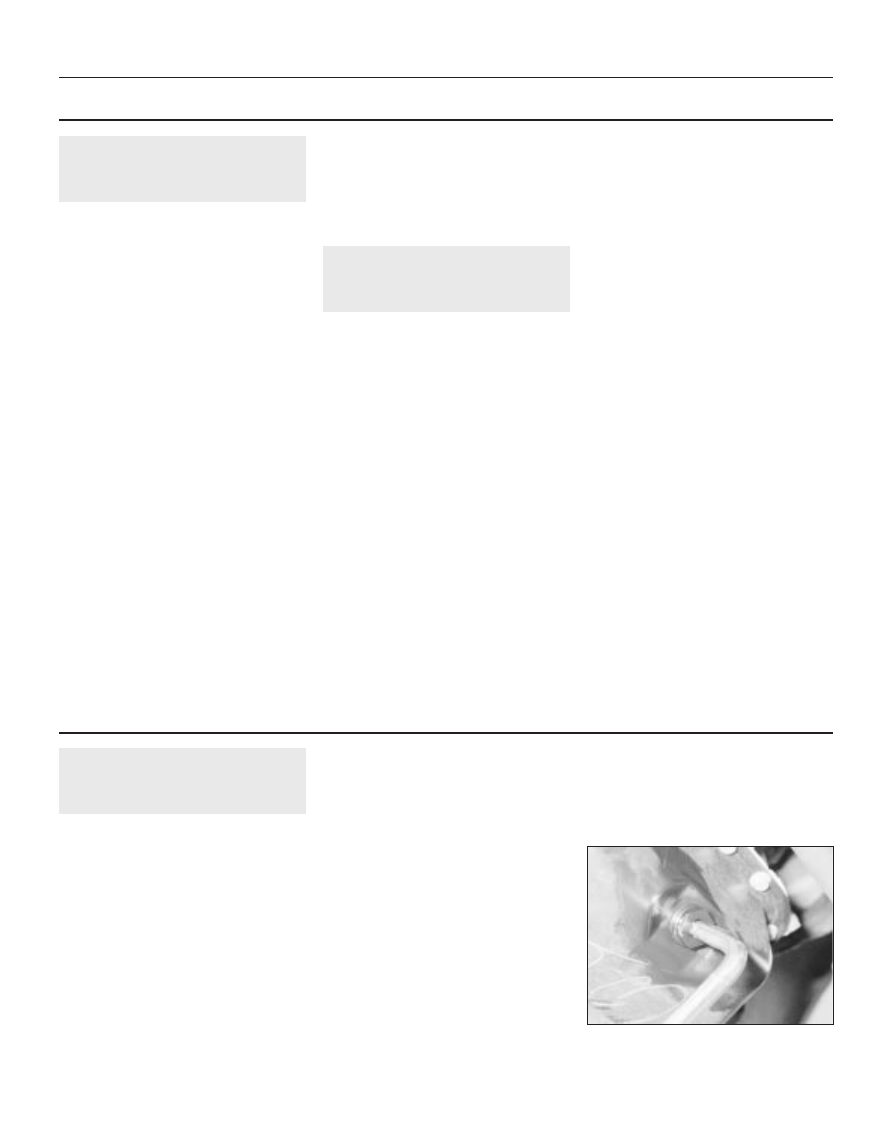
3 Slacken the drain plug about half a turn; on
some models, a square-section wrench may
be needed to slacken the plug (see
illustration). Position the draining container
under the drain plug, then remove the plug
completely. If possible, try to keep the plug
3.3 Slackening the sump drain plug with a
square-section wrench