содержание .. 69 70 71 72 ..
Peugeot 405. Manual - part 71
Special tools
The tools in this list are those which are not
used regularly, are expensive to buy, or which
need to be used in accordance with their
manufacturers’ instructions. Unless relatively
difficult mechanical jobs are undertaken
frequently, it will not be economic to buy
many of these tools. Where this is the case,
you could consider clubbing together with
friends (or joining a motorists’ club) to make a
joint purchase, or borrowing the tools against
a deposit from a local garage or tool hire
specialist. It is worth noting that many of the
larger DIY superstores now carry a large
range of special tools for hire at modest rates.
The following list contains only those tools
and instruments freely available to the public,
and not those special tools produced by the
vehicle manufacturer specifically for its dealer
network. You will find occasional references
to these manufacturers’ special tools in the
text of this manual. Generally, an alternative
method of doing the job without the vehicle
manufacturers’ special tool is given. However,
sometimes there is no alternative to using
them. Where this is the case and the relevant
tool cannot be bought or borrowed, you will
have to entrust the work to a dealer.
M Valve spring compressor
M Valve grinding tool
M Piston ring compressor
M Piston ring removal/installation tool
M Cylinder bore hone
M Balljoint separator
M Coil spring compressors (where applicable)
M Two/three-legged hub and bearing puller
M Impact screwdriver
M Micrometer and/or vernier calipers
M Dial gauge
M Stroboscopic timing light
M Dwell angle meter/tachometer
M Universal electrical multi-meter
M Cylinder compression gauge
M Hand-operated vacuum pump and gauge
M Clutch plate alignment set
M Brake shoe steady spring cup removal tool
M Bush and bearing removal/installation set
M Stud extractors
M Tap and die set
M Lifting tackle
M Trolley jack
Buying tools
Reputable motor accessory shops and
superstores often offer excellent quality tools
at discount prices, so it pays to shop around.
Remember, you don’t have to buy the most
expensive items on the shelf, but it is always
advisable to steer clear of the very cheap
tools. Beware of ‘bargains’ offered on market
stalls or at car boot sales. There are plenty of
good tools around at reasonable prices, but
always aim to purchase items which meet the
relevant national safety standards. If in doubt,
ask the proprietor or manager of the shop for
advice before making a purchase.
Care and maintenance of tools
Having purchased a reasonable tool kit, it is
necessary to keep the tools in a clean and
serviceable condition. After use, always wipe
off any dirt, grease and metal particles using a
clean, dry cloth, before putting the tools away.
Never leave them lying around after they have
been used. A simple tool rack on the garage
or workshop wall for items such as
screwdrivers and pliers is a good idea. Store
all normal spanners and sockets in a metal
box. Any measuring instruments, gauges,
meters, etc, must be carefully stored where
they cannot be damaged or become rusty.
Take a little care when tools are used.
Hammer heads inevitably become marked,
and screwdrivers lose the keen edge on their
blades from time to time. A little timely
attention with emery cloth or a file will soon
restore items like this to a good finish.
Working facilities
Not to be forgotten when discussing tools
is the workshop itself. If anything more than
routine maintenance is to be carried out, a
suitable working area becomes essential.
It is appreciated that many an owner-
mechanic is forced by circumstances to
remove an engine or similar item without the
benefit of a garage or workshop. Having done
this, any repairs should always be done under
the cover of a roof.
Wherever possible, any dismantling should
be done on a clean, flat workbench or table at
a suitable working height.
Any workbench needs a vice; one with a jaw
opening of 100 mm is suitable for most jobs.
As mentioned previously, some clean dry
storage space is also required for tools, as well
as for any lubricants, cleaning fluids, touch-up
paints etc, which become necessary.
Another item which may be required, and
which has a much more general usage, is an
electric drill with a chuck capacity of at least 8
mm. This, together with a good range of twist
drills, is virtually essential for fitting
accessories.
Last, but not least, always keep a supply of
old newspapers and clean, lint-free rags
available, and try to keep any working area as
clean as possible.
Tools and Working Facilities
REF•7
REF
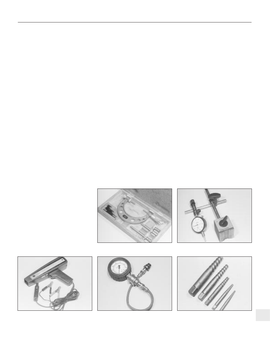
Stroboscopic timing light
Stud extractor set
Compression tester
Dial test indicator (“dial gauge”)
Micrometer set