Peugeot 405. Manual - part 67


  Главная      Peugeot     Peugeot 405 (1988-1997) - Service And Repair Manual Haynes


поиск по сайту            


содержание   ..  65  66  67  68   ..


Peugeot 405. Manual - part 67


BA White
GR Grey
MR Brown
BE Blue
RS Pink
VE Green

Connector colours

BG Beige
JN Yellow
RG Red
OR Orange
VI

Mauve

NR Black

B

A

C

D

E

F

G

H

J

K

L

M

2

1

3

4

5

6

7

8

B

A

C

D

E

F

G

H

J

K

L

M

2

1

3

4

5

6

7

8

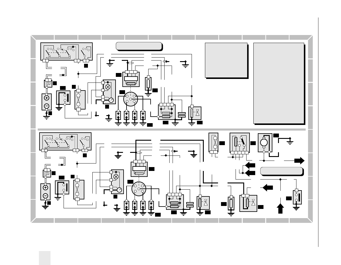
Diagram 4 : Engine systems (carburettor models) - later models

H29183

T.M.MARKE

2

1

3

Engine systems - carburettor

models without submerged pump

1

E000

2

1

GR

NR

4

1

2

2

1

2

BB5

BB10

2B

GR

F12

BE

1A

CC2

CC

GR

BE

JN

BA

7

4

b

e

6
4

5

E020

MPB

M4B

C120

420

1

2

3

4

HT

1

BE

3

2

1

NR

3

2 1

4

NR

1

VE

427

E005

MPR1

427

110

E040

MP

427

110

CC21/CC20

CC21

CC1

CC1

CC1

Key to items

1

Battery

2

Battery +ve control unit

3

Fusebox

4

Ignition switch

5

Instrument cluster
b = tachometer
e = choke warning light

23 Choke switch
24 Ignition module
25 Distributor
26 Spark plugs
27 Ignition coil
28 Carburettor breather solenoid
29 Carburettor/throttle housing

heater

30 Idle speed solenoid
31 Fuel pump fuse
32 Fuel pump relay
33 Fuel pump
34 Oil pressure switch

23

26

25

24

27

28

29

2

1

3

Engine systems - carburettor

models with submerged pump

1

E000

2

1

GR

NR

4

1

2

2

1

2

BB5

BB10

2B

GR

F12

BE

1A

CC2

CC

GR

BE

JN

BA

7

4

b

e

6
4

5

E020

MPB

M4B

C120

420

1

2

3

4

HT

1

BE

3

2

1

NR

3

2 1

4

NR

1

VE

427

E005

MPR1

427

110

E040

MP

427

110

CC21/CC20

CC21

CC1

CC1

CC1

23

26

25

24

27

28

29

NR

5

2

4

1

3

NR

2

1

M

E050

M121

121

2/G2

1030

C501

CC20

CC20/CC22

RG

1

2

8073

From air

conditioning

M801

M801

M801

2

GR

410

4120

4120

410

30

34

31

32

33

5/L6

1202

2/C2

5/M3

Wiring diagrams  12•45

12

E014

BA

2

1

BA 2 1

E015

VE

1

2

BE

2

1

BA White
GR Grey
MR Brown
BE Blue
RS Pink
VE Green

Connector colours

BG Beige
JN Yellow
RG Red
OR Orange
VI

Mauve

NR Black

B

A

C

D

E

F

G

H

J

K

L

M

2

1

3

4

5

6

7

8

B

A

C

D

E

F

G

H

J

K

L

M

2

1

3

4

5

6

7

8

Diagram 5 : Warning lights and gauges - later models

H29184

T.M.MARKE

Key to items

1

Battery

2

Battery +ve control unit

3

Fusebox

4

Ignition switch

5

Instrument cluster
f = coolant temp. gauge
g = oil temp./level gauge
h = high coolant temp. warning light
i = oil pressure gauge
j = stop warning light
k = pad wear warning light
l = catalytic converter warning light

m = handbrake/low brake fluid

warning light

n = low oil pressure warning light
o = low coolant warning light
p = fuel gauge
q = low fuel warning light
r = fuel gauge (submerged pump)
s = low fuel warning light

(submerged pump)

35 Engine oil level sensor
36 Engine oil temperature sensor

37 Coolant temperature sensor/switch
38 LH front pad wear sensor
39 RH front pad wear sensor
40 Oil pressure sensor/switch
41 Fuel gauge sender unit
42 Fuel gauge sender unit

(submerged pump)

43 Catalytic converter temperature sensor
44 Catalytic converter temperature control unit
45 Low brake fluid sender unit
46 Handbrake switch
47 Coolant level sensor

2

1

3

1

E000

2

1

GR

NR

4

1

2

2

1

2

BB5

BB10

GR

F12

BE

1A

CC2

CC

GR

F2

2B

3B

RG

6B

BA

VE

JN

f

h

j

o

JN

4

7

6

E020

M4E

MPB

CO23

401

CO23

401

400

400

C120

NR

3
2

1

E002

402

C123

g

BE

3

2

1

4

4

2

M4C

M4B

C120

n

C120

M4C

MMC2

M401

402

402

GR

2

1

412

410

410

412

BE

1

2

411

411

414

415

415

414

i

p

9

6

4

q

MR

3

1

2

E050

M430

430

430

431

431

r

s

MR

M

1

2

3 4 5

}

430

M430

M120

M120

4/M6

1202

430

k

m

8/H2

211

444

446

412

402

431

445

446

2

1

NR

2

1

NR

M44B

M44A

M440

M440

E005

MPR1

M441

441

441

440

4410

C12

3 2

1

NR

l

2

4

7 10 9

11

8

GR

MPR2

M480

485

485

485

C121

402

5

441

485

485

441

M440

485

441

M440

35

36

37

38

39

40

41

42

43

44

45

46

47

4/L8

410

12•46

Wiring diagrams

2
1

MR

2

1

B

A

C

D

E

F

G

H

J

K

L

M

2

1

3

4

5

6

7

8

B

A

C

D

E

F

G

H

J

K

L

M

2

1

3

4

5

6

7

8

Diagram 6 : External temp. display, clock and exterior lighting - later models

H29185

T.M.MARKE

3

1

6A

GR

F25

NR

F8

1

E000

Key to items

1

Battery

2

Battery +ve control unit

3

Fusebox

4

Ignition switch

5

Instrument cluster
t = analogue clock
u = sidelight warning light

48 Outside air temp. display
49 Digital clock
50 Outside air temp. sensor
51 Multi-function switch
52 Horn
53 RH front sidelight
54 LH front sidelight
55 Number plate light

56 RH rear light cluster (saloon)

a = direction indicator
b = tail light
c = brake light
d = foglight
e = reversing light

57 LH rear light cluster (saloon)

(see above)

BA White
GR Grey
MR Brown
BE Blue
RS Pink
VE Green

Connector colours

BG Beige
JN Yellow
RG Red
OR Orange
VI

Mauve

NR Black

2

NR

BB1

BA

t

1 2

5

E020

B252

M4C

MPB

Analogue clock

2

1

1

E000

2

1

GR

NR

1

2

2

1

4

2

BB5

BB10

AA2

GR

3

1

F25

NR

F8

1

GR

F28

MR

6A 5B

Digital clock/outside

air temp. display

NR

2

1

BB1

2

1

3 4 5 6 7

GR

2

1

3 4

GR

BA

2

1

B251

B253

B253

721

722

721

722

A283

A285

A285

8/C3

V193

A283

B251

V196

V19B

E020

MPB

M722

M72A

3A

1A

BA

NR

1

2

2

1

3

1

5A

VE

F7

NR

1

2

NR

250

1

2

NR

E000

E001 E002

MMC1

MMC2

M250

M251

251

252

BB1

BO7

Horns

48

49

50

51

52

52

BA

3B

2B

51

2

1

1

E000

2

GR

BB5

BB7

MR

2
3
4

5

6

1

MR

5
4

3

2

1

6

MR

2

1

3

GR

F9

RG

VE

F4

BE

7B

2B

2A

1B

VV1

VV7

MV2

MV1

MV1

V094

V095

V094

2
1

MR

Side, tail and number

plate lights (saloon)

VO9

VO4

E050

M26A

M26B

2

1

MR

2

1

MR

V092

V091

E001

MMC1

MV2

MV1

E002

MMC2

VO4

VO9

V090

2

BA

1

JN

u

E002

V096

M4C

MPB

VO9

VO4

V094
MV1

5

53

54

55

55

56

57

a

b

c

d

e

a

b

c

d

e

VO4

Wiring diagrams  12•47

12

R

C

M

NR

Main

Dip

NR

1

E002

MMC2

MPR9

MP2

MPR8

MP1

PC3

PC4

PR4

PR3

PR9

PR8

E001

MMC1

B

A

C

D

E

F

G

H

J

K

L

M

2

1

3

4

5

6

7

8

B

A

C

D

E

F

G

H

J

K

L

M

2

1

3

4

5

6

7

8

Diagram 7 : Exterior lighting continued - later models

H29186

T.M.MARKE

Key to items

1

Battery

2

Battery +ve control unit

3

Fusebox

4

Ignition switch

5

Instrument cluster
v = dip beam warning light
w = main beam warning light

51 Multi-function switch
55 Number plate light
58 RH tailgate light cluster (estate)

d = foglight
e = reversing light

59 LH tailgate light cluster (estate)

(see above)

60 RH headlight
61 RH driving light
62 LH driving light
63 LH headlight

64 Dim-dip relay B
65 Driving light relay
66 Dim-dip relay A
67 Dim-dip resistor
73 RH rear light cluster (estate)

a = direction indicator
b = tail light
c = brake light

74 LH rear light cluster (estate)

(see above)

BA White
GR Grey
MR Brown
BE Blue
RS Pink
VE Green

Connector colours

BG Beige
JN Yellow
RG Red
OR Orange
VI

Mauve

NR Black

BA

3B

2B

51

2

1

1

E000

2

GR

BB5

VO9D

3

F9

RG

VE

F4

BE

2B

2A

1B

VV1

VV7

Tail and number

plate lights (estate)

BE

2

1

4

3

a

b

c

BE

2

1
4

3

a

b

c

BE

d

e

MR

2

1

4

1

2

3

MR

2

1

M26A

BE

d

e

MR

2

1

1

4

3

2

MR

2

1

M26

VO9G

3 4

1

2

BE

M95

VO95

VO4

VO4

E054

M26A

VO9

VO94

VO9

VO4

VO9

M268B

M94

E052

E053

MV

2

1

1

E000

2

1

GR

NR

4

1

2

2

1

2

BB5

BB10

GR

JN

5

4

BA

JN

2

2

v

w

E020

MPB

M4C

M4E

6B

RG

F12

BE

1A

CC2

CC

BA

3B

2B

1B

51

NR

3B

2B

5B

1A

BB6

BB9

BB8

BB5

NR

1

R

C

M

NR

Main

Dip

1

2

5

4

3

MR

5

2

1

3

VE

3

2

1

NR

E005

M240

MPR2

M268

MPR1

245

C12

C122

PC1

PR5

PC1

VV1

VV1

PR10

246

PC7

PC7

PC5

BB19

BB17

BB18

PR7

PR7

BB19

PC1

PR11

245

PR10

PC5

PR1

PR1

PR5

5

2

1

3

VE

Headlights

73

58

55

55

74

59

5

3

60

61

62

63

64

65

66

67

BB7

12•48

Wiring diagrams


содержание   ..  65  66  67  68   ..