Peugeot 405. Manual - part 66


  Главная      Peugeot     Peugeot 405 (1988-1997) - Service And Repair Manual Haynes


поиск по сайту            


содержание   ..  64  65  66  67   ..


Peugeot 405. Manual - part 66


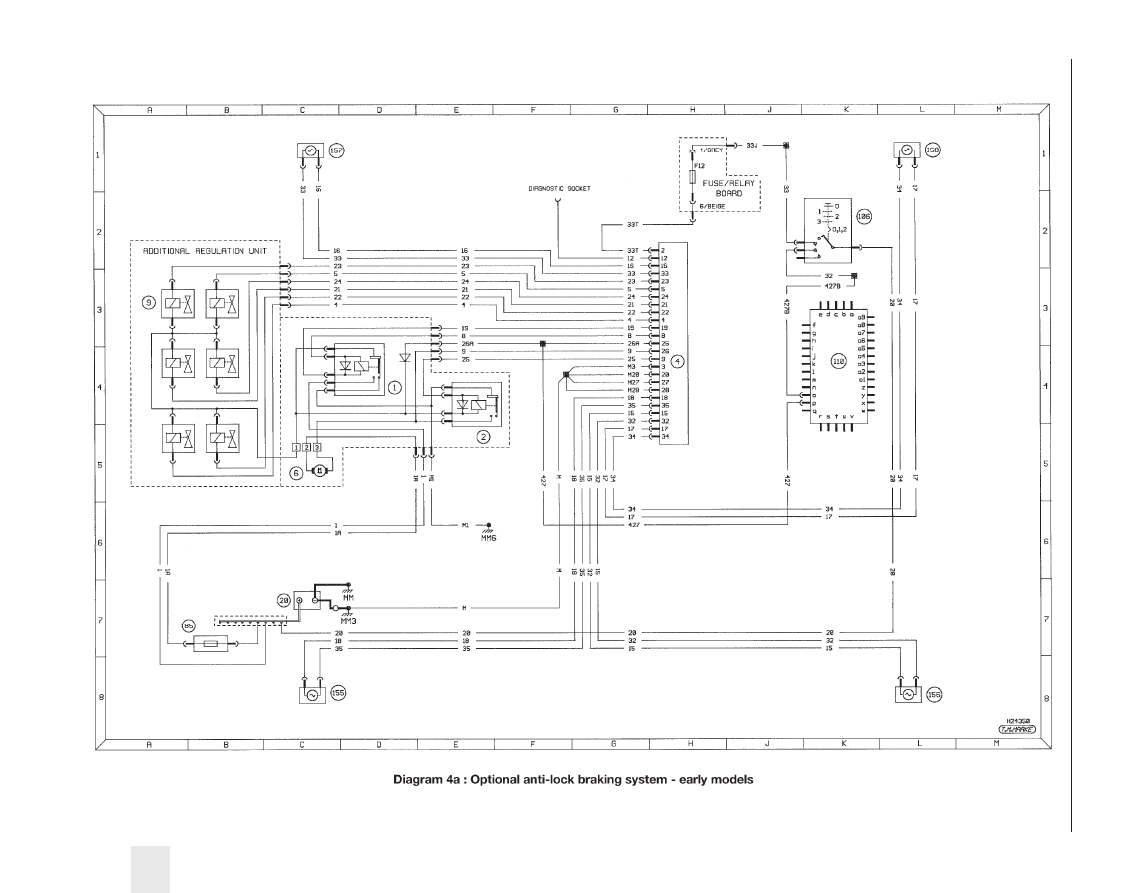
Wiring diagrams  12•41

12

B

A

C

D

E

F

G

H

J

K

L

M

2

1

3

4

5

6

7

8

B

A

C

D

E

F

G

H

J

K

L

M

2

1

3

4

5

6

7

8

Diagram 1 : Notes, fuses, key to symbols and earth locations - later models

H29180

T.M.MARKE

Notes

1.

Wire identification is not by colour, but by
letters or numbers appearing on the wire
at each end.

2.

Wires may interconnect between diagrams
and are located by using a grid reference
e.g. 2/A1 denotes a position on diagram 2
grid location A1.

3.

Brackets show how circuits may be wired
in more than one way.

4.

Not all items are fitted to all models.

Fuse Rating

Circuit

F1

10A

Radio (accessories +ve)

F1A

10A

Radio (battery +ve)

F2

5A

Air conditioning, instrument panel, interior light time delay, selector illumination

F3

Spare

F4

10A

Lights on buzzer, RH tail light

F5

15A

Engine cooling fan/coolant temperature control unit relay, air conditioning

F6

10A

ABS control unit

F7

20A

Horn

F8

Shunt

F9

5A

LH tail light, front sidelights, sidelight warning light, number plate light

F10

30A

Rear electric windows

F11

Spare

F12

10A

Reversing light, cruise control, handbrake warning light, alarm siren and control unit

F13

Spare

F14

30A

Electric seats, alarm

F15

30A

Central locking, front/rear interior lights, luggage compartment light, electric aerial,
interior light time delay

F16

20A

Cigar lighter (battery +ve)

F16A 20A

Cigar lighter (accessories +ve)

F17

Spare

F18

10A

Rear fog lights

F19

10A

Sidelights, instrument panel illumination, dimmer switch

F20

30A

Heated front seats

F21

30A

Air conditioning

F22

20A

Tailgate wiper

F23

15A

Heated rear window switch

F24

30A

Windscreen wipers, supply to control unit cruise control interface

F25

5A

Radio memory, clock, engine cooling fan relay at low rpm

F26

30A

Hazard warning light switch

F27

30A

Heated rear screen, heated mirrors

F28

15A

Instrument panel, digital clock, height adjustment control unit, stop lights,
differential lock, ride height adjustment

F29

30A

Front electric windows, sunroof

F30

15A

Map reading light, courtesy mirror light, glovebox light, lights on buzzer, indicators,
electric mirror adjustment, electric window one-touch operation, rear electric
window relay

1

2

3

4

5

6

7

8

10

11

12

13

14

15

16

9

17

18

19

20

21

22

23

25

26

27

28

29

30

24

Passenger compartment

fusebox

Key to symbols

Switch

7

Fuse

Item no.

Pump/motor

Earth

Connecting wires

Bulb

3/B2

3/B2

Connection to other
circuits (e.g. diagram
3/grid location B2).
Direction of arrow
denotes current flow.

Resistor

Variable
resistor

Diode

Solenoid actuator

Wire-battery positive
potential (double line)

Wire-battery negative
potential (thick line)

Wire-interconnecting
(thin line)

NR

2 1

GR

1 2

Dashed line denotes
part of larger item

M

F13

Earth locations

E000

Near battery

E001

LH side of front panel (in engine compartment)

E002

RH side of front panel (in engine compartment)

E005

LH side of bulkhead (in engine compartment)

E006

RH side of parcel shelf

E020

LH kick panel (in passenger compartment)

E040

On gearbox

E050

Centre of rear panel (in luggage compartment)

E052

Inside tailgate (estate)

E053

LH rear corner of luggage compartment (estate)

E054

RH rear corner of luggage compartment (estate)

E081

LH side of bulkhead (in engine compartment)

12•42

Wiring diagrams

BA White
GR Grey
MR Brown
BE Blue
RS Pink
VE Green

Connector colours

BG Beige
JN Yellow
RG Red
OR Orange
VI

Mauve

NR Black

2

1

B

A

C

D

E

F

G

H

J

K

L

M

2

1

3

4

5

6

7

8

B

A

C

D

E

F

G

H

J

K

L

M

2

1

3

4

5

6

7

8

Diagram 2 : Starting, charging and preheating - later models

H29181

T.M.MARKE

G

3

Starting and

charging system -

manual transmission

petrol models

1

E000

M

Key to items

1

Battery

2

Battery +ve control unit

3

Fusebox

4

Ignition switch

5

Instrument cluster
a = no charge warning light
b = tachometer
c = water in fuel warning light
d = glow plug warning light

6

Alternator

7

Starter motor

8

Starter inhibitor switch/reversing
light switch (automatic transmission)

9

Starter safety relay

10 Water in fuel sensor
11 TDC sensor
12 Fuel cut off solenoid valve
13 Preheat control unit
14 Glow plugs

2

1

GR

NR

4

1

2

2

1

1

4B

GR

F28

MR

2

BB5

BB10

AA2

7 8

VE

a

A28

BB17

BB18

100

100

1070

1070

5

7

6

2

1

G

3

Starting and charging system - automatic

transmission petrol models

1

E000

M

2

1

GR

NR

4

1

2

2

1

1

4B

GR

F28

MR

2

BB5

BB10

AA2

7 8

VE

a

A28

BB17

BB18

100

108

1070

1070

5

7

6

6B

RG

F12

BE

1A

109

CC2

NR

2B 1A

1

2

5

4

3

VI

E040

MP

M106

C128

C12

106

108

108

108

8

9

2

1

G

3

Starting, charging and preheating

system - non turbo diesel

1

E000

M

2

1

GR

NR

4

1

2

2

1

1

GR

F28

MR

2

BB5

BB10

AA2

8
7

VE

a

BE

JN

BA

9
3

2
4

b

c

d

5

A28

100

1070

7

6

6B

RG

F12

BE

1A

CC2

CC

CC

1070

4B 2B

3

5

1

4

118

E020

MPB

M4C

M4B

C120

C120

A28

1070

C120

1070

A28

7

4

6

3

1

2

MR

426

428

429

427

D428

E005

MPR1

E040

MP

M115

VE

CC5

CC5

105

105

435

BB18

BB18

1070

100

BB15

BB15

BB15

BB15

CC6

1

3

2

NR

M405

403

403

C12

C129

12

11

10

13

14

GR

GR

GR

4/K6

1030

1030

4/K6

Wiring diagrams  12•43

12

VE

2

1

5

2

4

1

3

VI

B

A

C

D

E

F

G

H

J

K

L

M

2

1

3

4

5

6

7

8

B

A

C

D

E

F

G

H

J

K

L

M

2

1

3

4

5

6

7

8

Diagram 3 : Preheating (turbo diesel) and engine cooling fans -later models

H29182

T.M.MARKE

Key to items

1

Battery

2

Battery +ve control unit
a = engine cooling fan fuse(s)

3

Fusebox

4

Ignition switch

5

Instrument cluster
a = no charge warning light
b = tachometer
c = water in fuel warning light
d = glow plug warning light

6

Alternator

7

Starter motor

10 Water in fuel sensor
11 TDC sensor
13 Preheat control unit
14 Glow plugs
15 Diesel advance corrector relay

16 Post heat thermal switch
17 Post heat relay
18 Diesel pump (advance corrector/

fuel cut off solenoid)

19 Cooling fan relay
20 Cooling fan thermal switch
21 Cooling fan
22 Two speed fan resistor

BA White
GR Grey
MR Brown
BE Blue
RS Pink
VE Green

Connector colours

BG Beige
JN Yellow
RG Red
OR Orange
VI

Mauve

NR Black

2

1

G

3

Starting,charging and

preheating system - turbo diesel

1

E000

M

2

1

GR

NR

4

1

2

2

1

1

GR

F28

MR

2

BB5

BB10

AA2

8
7

VE

a

BE

JN

BA

9
3

2
4

b

c

d

5

A28

100

1070

7

6

6B

RG

F12

BE

1A

CC2

CC

1070

4B 2B

118

E020

MPB

M4C

M4B

C120

C120

A28

1070

C120

1070

A28

7

4

6

3

1

2

MR

426

428

429

427

D428

E005

MPR1

E040

MP

M115

VE

CC5

CC5

105

105

435

BB18

BB18

1070

100

BB15

BB15

BB15

BB15

1

3

2

NR

M405

403

403

C12

C129

11

10

13

14

5

2

4

1

3

VI

2

1

3

NR

BE

2

1

M11A/M120

M11A/M120

M11A

M120

1395

1397

1397

1396

3

5

1

4

2

1395

1394

1394

403

CC14

CC12

CC6

CC16

1398

1398

CC15

16

15

17

18

2

1

1

E000

2

BE

3

2

1

1

3

2

NR

1 2

NR

M

E001

5

2

4

1

3

NR

M150

M15E

157

153

1540

B40

B401/B40

152

Single cooling fan

GR

MR

a

1

E000

2

MR

a

a

NR

5

2

4

1

3

NR

5

2

4

1

3

NR

5

2

4

1

3

1 2

NR

M

1 2

NR

M

BE

3

2

1

Twin cooling fans

E001

M15D

E002

M15B

156

1550

M15A

154

158

157

M15B

MMC1

M15D

159

1

2

B40

B412

B41

B413

B411

B41/B410

B40

159

157

19

21

19

19

19

21

21

22

20

20

12•44

Wiring diagrams


содержание   ..  64  65  66  67   ..