содержание .. 42 43 44 45 ..
Peugeot 405. Manual - part 44
13 Master cylinder - removal,
overhaul and refitting
3
Removal
1 Disconnect the battery negative lead.
2 Remove the cap from the brake fluid
reservoir, place a piece of polythene sheet
over the filler neck, and refit the cap tightly.
Alternatively, siphon all the fluid from the
reservoir using an old teat pipette or poultry
baster. This will minimise fluid loss during the
following procedure.
3 To improve the clearance available for
removal, remove the windscreen wiper arms
(see Chapter 12), then remove the scuttle
cover panel from the front edge of the
windscreen (see Chapter 11).
4 Disconnect the wiring from the low brake
fluid level warning sensor.
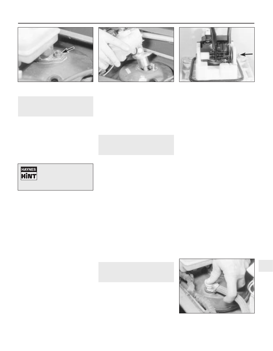
5 Unscrew the two nuts securing the master
cylinder to the brake vacuum servo unit (see
illustration).
6 Unscrew the union nuts, and disconnect
the brake fluid pipes from the master cylinder.
7 Lift the master cylinder, complete with the fluid
reservoir, from the servo unit (see illustration).
Hold a cloth under the assembly to catch any
fluid spillage. Recover the sealing ring.
8 Unscrew the clamp nut and bolt, release
the plastic clamp, and withdraw the fluid
reservoir from the master cylinder.
Overhaul
9 No spare parts are available from Peugeot
for the master cylinder, and if faulty the
complete unit must be renewed.
Refitting
10 Refitting is a reversal of removal, bearing
in mind the following points.
a) Examine the master cylinder sealing ring
and renew if necessary.
b) Ensure that the brake pipe union nuts are
securely tightened.
c) Refit the windscreen wiper arms with
reference to Chapter 12.
d) On completion, remove the polythene,
where applicable, then top-up and bleed
the hydraulic system as described in
Section 2.
14 Brake pedal -
removal and refitting
4
Note: On models fitted with the Bendix
“integral” ABS, the hydraulic modulator unit
must be removed in order to remove the brake
pedal. This task must be entrusted to a
Peugeot dealer - see Section 23.
Removal
1 The pedal assembly is removed complete
with the vacuum servo, and the procedure is
described in Section 15.
2 With the servo/pedal assembly removed,
proceed as follows.
3 Remove the securing clip, and withdraw the
pin securing the servo pushrod to the pedal.
4 Unscrew the nut from the pedal pivot bolt,
and withdraw the pivot bolt to release the
pedals (see illustration).
Refitting
5 Refitting is a reversal of removal, but renew
the nylon pedal pivot bushes if they are worn,
and refit the servo/pedal assembly as
described in Section 15.
15 Vacuum servo unit - testing,
removal and refitting
4
Testing
1 To test the operation of the servo unit,
depress the footbrake several times to
exhaust the vacuum, then start the engine
whilst keeping the pedal firmly depressed. As
the engine starts, there should be a noticeable
“give” in the brake pedal as the vacuum builds
up. Allow the engine to run for at least two
minutes, then switch it off. If the brake pedal
is now depressed it should feel normal, but
further applications should result in the pedal
feeling firmer, with the pedal stroke
decreasing with each application.
2 If the servo does not operate as described,
first inspect the servo unit check valve as
described in Section 16.
3 If the servo unit still fails to operate satisfac-
torily, the fault lies within the unit itself.
Repairs to the unit are not possible - if faulty,
the servo unit must be renewed.
Removal
4 Disconnect the battery negative lead.
5 Remove the windscreen wiper motor/
linkage assembly as described in Chapter 12.
6 Disconnect the wiring from the low brake
fluid level warning sensor.
7 Pull the vacuum check valve from the
grommet in the top of the servo (see
illustration).
8 Unscrew the two nuts securing the master
cylinder to the brake vacuum servo unit, then
ease the master cylinder up to disengage it
from the servo, without disconnecting the
fluid pipes. Take care not to strain the fluid
pipes. If necessary, release the fluid pipes
from their locating clips to enable them to
move sufficiently.
9 Working in the driver’s footwell, remove the
carpet trim panel from under the facia to
expose the pedal assemblies.
10 Where applicable, working under the
facia, unscrew the bolts securing the relay
bracket and the wiring connector bracket(s) to
improve access.
Braking system 9•15
14.4 Pedal pivot bolt and nut (arrowed)
15.7 Pulling the vacuum check valve from
the servo
13.7 Removing the master cylinder from
the vacuum servo
13.5 Master cylinder securing nut
(arrowed)
9
Spread some cloth over the
vacuum servo unit and
surrounding area to catch
fluid drips as the master
cylinder is removed.