содержание .. 38 39 40 41 ..
Peugeot 405. Manual - part 40
from the end of the distributor body and
discard it; a new one must be used on
refitting.
Integral ignition system with
distributor
5 Disconnect the battery negative terminal. If
necessary, to improve access to the
distributor, remove the airflow meter as
described in Chapter 4.
6 Peel back the waterproof cover, slacken
and remove the distributor cap retaining
screws, then remove the cap and position it
clear of the distributor body. Recover the seal
from the cap. If necessary, disconnect the HT
leads from the spark plugs after noting their
positions - on 16-valve engines it will be
necessary to remove the cover plate over the
spark plugs.
7 On 8-valve engines slacken and remove the
two mounting bolts and washers, and
withdraw the distributor from the cylinder
head. Remove the O-ring from the end of the
distributor body, and discard it; a new one
must be used on refitting.
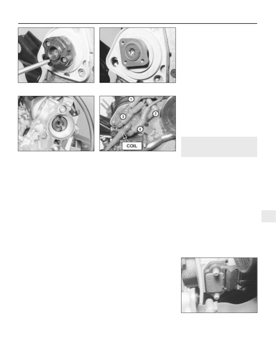
8 On XU9J4 16-valve engines undo the three
Torx-headed screws securing the rotor to the
rotor drive flange and lift off the rotor, then
unscrew the screw from the centre of the
drive flange and withdraw the flange. Remove
the plastic base plate from the end of the
cylinder head (see illustrations).
Refitting
Breakerless ignition system
9 Lubricate the new O-ring with a smear of
engine oil and fit it to the groove in the
distributor body. Examine the distributor cap
seal for wear or damage and renew if
necessary.
10 Align the distributor rotor shaft drive
coupling key with the slots in the camshaft
end noting that the slots are offset to ensure
that the distributor can only be fitted in one
position (see illustration). Carefully insert the
distributor into the cylinder head whilst
rotating the rotor arm slightly to ensure that
the coupling is correctly engaged. Refit the
distributor retaining nuts, tightening them
lightly only.
11 Ensure that the seal is correctly located in
its groove then refit the cap assembly to the
distributor and tighten its retaining screws
securely. Fold the waterproof cover back over
the distributor cap ensuring it is correctly
located. Where necessary reconnect the HT
leads to the spark plugs.
12 Reconnect the vacuum hose to the
diaphragm unit and the distributor wiring
connector. Where necessary, refit the ignition
HT coil as described in Section 3, and the inlet
duct as described in Chapter 4.
13 Reconnect the battery negative terminal,
then check and if necessary adjust the ignition
timing as described in Section 6. Tighten the
distributor mounting nuts to the specified
torque.
Integral ignition system
with distributor
14 On XU9J4 16-valve engines refit the
plastic base plate to the end of the cylinder
head, then refit the drive flange using locking
fluid on the threads of the drive flange screw.
Tighten the centre screw. Refit the rotor and
tighten the Torx-headed screws.
15 On 8-valve engines lubricate the new O-
ring with a smear of engine oil and fit it to the
groove in the distributor body. Examine the
distributor cap seal for wear or damage and
renew if necessary. Align the distributor rotor
shaft drive coupling key with the slots in the
camshaft end noting that the slots are offset
to ensure that the distributor can only be fitted
in one position. Carefully insert the distributor
into the cylinder head whilst rotating the rotor
arm slightly to ensure that the coupling is
correctly engaged. Refit the distributor
retaining nuts, tightening them securely.
16 Ensure that the seal is correctly located in
its groove then refit the cap assembly to the
distributor and tighten its retaining screws
securely. Fold the waterproof cover back over
the distributor cap ensuring it is correctly
located.
17 Where necessary reconnect the HT leads
to the spark plugs (see illustration) and
on 16-valve engines refit the cover plate.
5
Ignition system amplifier
unit(s) - removal and refitting
2
Removal
1 Disconnect the battery negative terminal.
Breakerless ignition system
2 The amplifier unit is mounted onto the side
of the distributor body (see illustration). To
improve access to the unit, disengage the hot
air inlet hose from the control valve and
manifold shroud and remove it from the
vehicle.
3 Disconnect the wiring connector then undo
the two retaining screws and remove the
amplifier unit.
Integral ignition system
4 The amplifier unit is located in the right-
hand rear corner of the engine compartment.
5 To remove the unit, disconnect the wiring
connector, undo the two retaining screws and
remove the amplifier from its mounting
bracket.
Ignition system 5B•5
4.10 Off-set drive slots on the camshaft
5.2 On breakerless ignition systems the
amplifier unit is mounted on the side
of the distributor body
4.17 Distributor cap and HT leads on the
XU9J4 16-valve model
4.8b Rotor drive flange
4.8a On XU9J4 16-valve engines undo the
rotor screws and remove the rotor
5B