Peugeot 405. Manual - part 24


  Главная      Peugeot     Peugeot 405 (1988-1997) - Service And Repair Manual Haynes


поиск по сайту            


содержание   ..  22  23  24  25   ..


Peugeot 405. Manual - part 24


correct reassembly. Discard the circlips - new
ones must be used on refitting.
16 Examine the gudgeon pin and connecting
rod small-end bearing for signs of wear or
damage. Wear can be cured by renewing both
the pin and bush. Bush renewal, however, is a
specialist job - press facilities are required,
and the new bush must be reamed accurately.
17 The connecting rods themselves should
not be in need of renewal, unless seizure or
some other major mechanical failure has
occurred. Check the alignment of the
connecting rods visually, and if the rods are
not straight, take them to an engine overhaul
specialist for a more detailed check.
18 Examine all components, and obtain any
new parts from your Peugeot dealer. If new
pistons are purchased, they will be supplied
complete with gudgeon pins and circlips.
Circlips can also be purchased individually.
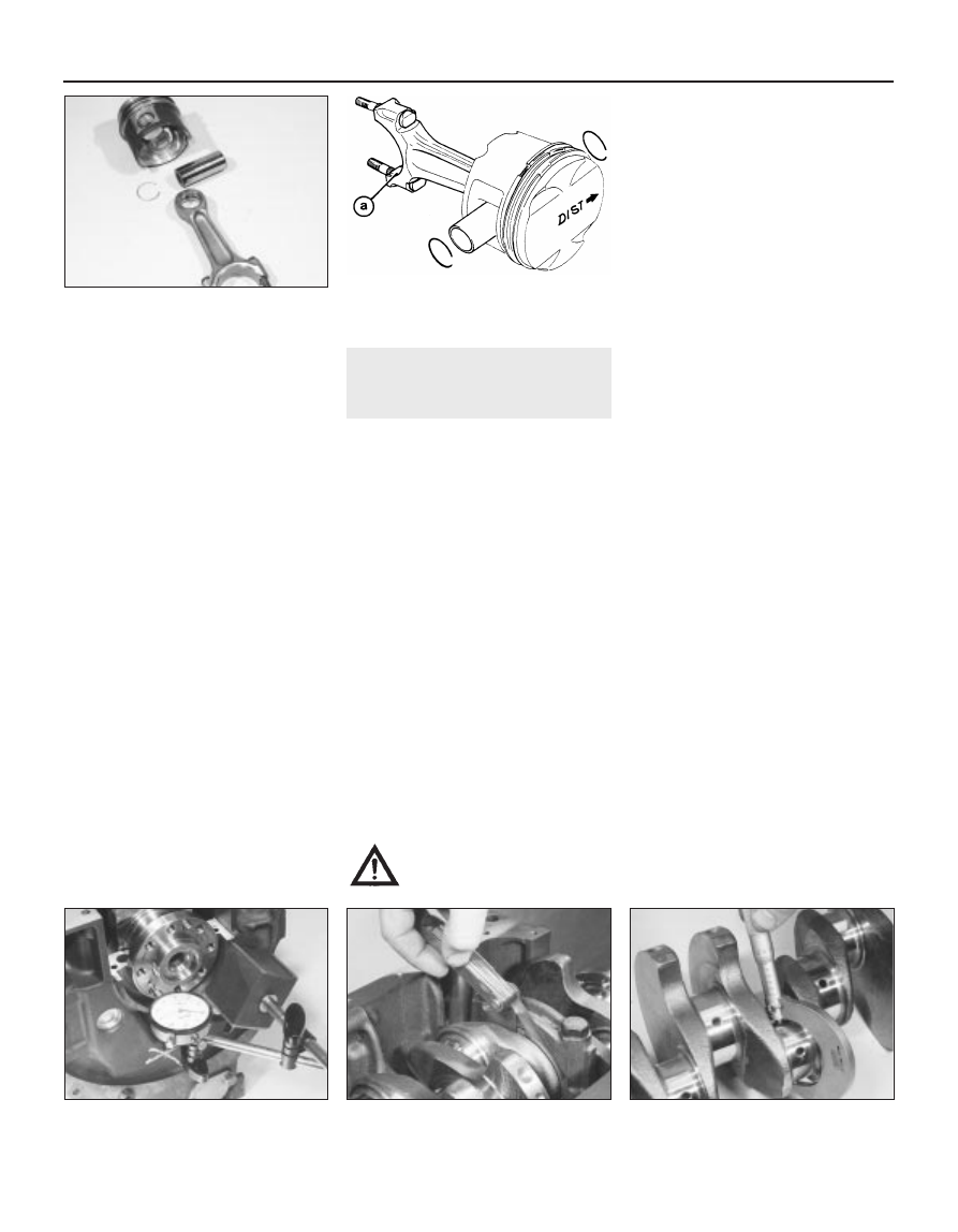
19 Position the piston so that the arrow on
the piston crown is positioned as shown in
relation to the connecting rod big-end bearing
shell cutouts (see illustration). Apply a smear
of clean engine oil to the gudgeon pin. Slide it
into the piston and through the connecting
rod small-end. Check that the piston pivots
freely on the rod, then secure the gudgeon pin
in position with two new circlips. Ensure that
each circlip is correctly located in its groove in
the piston.

14 Crankshaft - inspection

2

Checking crankshaft endfloat

If the crankshaft endfloat is to be checked,
this must be done when the crankshaft is still
installed in the cylinder block/crankcase, but
is free to move (see Section 11).
Check the endfloat using a dial gauge in
contact with the end of the crankshaft. Push
the crankshaft fully one way, and then zero
the gauge. Push the crankshaft fully the other
way, and check the endfloat. The result can
be compared with the specified amount, and
will give an indication as to whether new
thrustwashers are required (see illustration).
If a dial gauge is not available, feeler blades
can be used. First push the crankshaft fully
towards the flywheel/driveplate end of the
engine, then use feeler blades to measure the
gap between the web of No 2 crankpin and
the thrustwasher (see illustration).

Inspection

Clean the crankshaft using paraffin or a
suitable solvent, and dry it, preferably with
compressed air if available. Be sure to clean
the oil holes with a pipe cleaner or similar
probe, to ensure that they are not obstructed.

Check the main and big-end bearing
journals for uneven wear, scoring, pitting and
cracking.
Big-end bearing wear is accompanied by
distinct metallic knocking when the engine is
running (particularly noticeable when the
engine is pulling from low speed) and some
loss of oil pressure.
Main bearing wear is accompanied by
severe engine vibration and rumble - getting
progressively worse as engine speed
increases - and again by loss of oil pressure.
Check the bearing journal for roughness by
running a finger lightly over the bearing
surface. Any roughness (which will be
accompanied by obvious bearing wear)
indicates that the crankshaft requires
regrinding (where possible) or renewal.
If the crankshaft has been reground, check
for burrs around the crankshaft oil holes (the
holes are usually chamfered, so burrs should
not be a problem unless regrinding has been
carried out carelessly). Remove any burrs with
a fine file or scraper, and thoroughly clean the
oil holes as described previously.
10 Using a micrometer, measure the
diameter of the main and big-end bearing
journals, and compare the results with the
Specifications 

(see illustration). By

measuring the diameter at a number of points
around each journal’s circumference, you will
be able to determine whether or not the
journal is out-of-round. Take the
measurement at each end of the journal, near
the webs, to determine if the journal is
tapered. Compare the results obtained with
those given in the Specifications. Where no
specified journal diameters are quoted, seek
the advice of a Peugeot dealer.
11 Check the oil seal contact surfaces at
each end of the crankshaft for wear and
damage. If the seal has worn a deep groove in
the surface of the crankshaft, consult an
engine overhaul specialist; repair may be
possible, but otherwise a new crankshaft will
be required.
12 At the time of writing, it was not clear
whether Peugeot produce oversize bearing
shells for all of these engines. On some
engines, if the crankshaft journals have not
already been reground, it may be possible to
have the crankshaft reconditioned, and to fit

14.10  Measuring a crankshaft big-end

journal diameter

2C•14 Engine removal and overhaul

13.15c  Piston and connecting rod

components

14.3  Checking crankshaft endfloat 

using feeler gauges

14.2  Checking crankshaft endfloat 

using a dial gauge

13.19  On 16-valve engines, on refitting

ensure that the piston arrow is positioned

as shown, in relation to the connecting rod

bearing shell cutout (a)

Warning: Wear eye protection
when using compressed air!

undersize shells (see Section 18). If no
undersize shells are available and the
crankshaft has worn beyond the specified
limits, it will have to be renewed. Consult your
Peugeot dealer or engine specialist for further
information on parts availability.

15 Main and big-end bearings -

inspection

2

Even though the main and big-end bearings
should be renewed during the engine
overhaul, the old bearings should be retained
for close examination, as they may reveal
valuable information about the condition of
the engine. The bearing shells are graded by
thickness, the grade of each shell being
indicated by the colour code marked on it.
Bearing failure can occur due to lack of
lubrication, the presence of dirt or other
foreign particles, overloading the engine, or
corrosion (see illustration). Regardless of the
cause of bearing failure, the cause must be
corrected (where applicable) before the
engine is reassembled, to prevent it from
happening again.
When examining the bearing shells, remove
them from the cylinder block/crankcase, the
main bearing ladder/caps (as appropriate), the
connecting rods and the connecting rod big-
end bearing caps. Lay them out on a clean
surface in the same general position as their
location in the engine. This will enable you to
match any bearing problems with the
corresponding crankshaft journal. Do not
touch any shell’s bearing surface with your
fingers while checking it, or the delicate
surface may be scratched.
Dirt and other foreign matter gets into the
engine in a variety of ways. It may be left in
the engine during assembly, or it may pass
through filters or the crankcase ventilation
system. It may get into the oil, and from there
into the bearings. Metal chips from machining
operations and normal engine wear are often
present. Abrasives are sometimes left in
engine components after reconditioning,
especially when parts are not thoroughly
cleaned using the proper cleaning methods.
Whatever the source, these foreign objects
often end up embedded in the soft bearing
material, and are easily recognised. Large
particles will not embed in the bearing, and
will score or gouge the bearing and journal.
The best prevention for this cause of bearing
failure is to clean all parts thoroughly, and
keep everything spotlessly-clean during
engine assembly. Frequent and regular engine
oil and filter changes are also recommended.
Lack of lubrication (or lubrication
breakdown) has a number of interrelated
causes. Excessive heat (which thins the oil),
overloading (which squeezes the oil from the
bearing face) and oil leakage (from excessive
bearing clearances, worn oil pump or high
engine speeds) all contribute to lubrication

breakdown. Blocked oil passages, which
usually are the result of misaligned oil holes in
a bearing shell, will also oil-starve a bearing,
and destroy it. When lack of lubrication is the
cause of bearing failure, the bearing material
is wiped or extruded from the steel backing of
the bearing. Temperatures may increase to
the point where the steel backing turns blue
from overheating.
Driving habits can have a definite effect on
bearing life. Full-throttle, low-speed operation
(labouring the engine) puts very high loads on
bearings, tending to squeeze out the oil film.
These loads cause the bearings to flex, which
produces fine cracks in the bearing face
(fatigue failure). Eventually, the bearing
material will loosen in pieces, and tear away
from the steel backing.
Short-distance driving leads to corrosion of
bearings, because insufficient engine heat is
produced to drive off the condensed water
and corrosive gases. These products collect
in the engine oil, forming acid and sludge. As
the oil is carried to the engine bearings, the
acid attacks and corrodes the bearing
material.
Incorrect bearing installation during engine
assembly will lead to bearing failure as well.
Tight-fitting bearings leave insufficient bearing
running clearance, and will result in oil
starvation. Dirt or foreign particles trapped
behind a bearing shell result in high spots on
the bearing, which lead to failure.
Do not touch any shell’s bearing surface
with your fingers during reassembly; there is a
risk of scratching the delicate surface, or of
depositing particles of dirt on it.
10 As mentioned at the beginning of this
Section, the bearing shells should be renewed
as a matter of course during engine overhaul;
to do otherwise is false economy. Refer to
Section 18 for details of bearing shell
selection.

16 Engine overhaul - reassembly

sequence

Before reassembly begins, ensure that all
new parts have been obtained, and that all
necessary tools are available. Read through
the entire procedure carefully to familiarise
yourself with the work involved, and to ensure
that all items necessary for reassembly of the
engine are at hand. In addition to all normal
tools and materials, thread-locking compound
will be needed. A suitable tube of liquid
sealant will also be required for the joint faces
that are fitted without gaskets. It is
recommended that Peugeot’s own product(s)
are used, which are specially formulated for
this purpose.
In order to save time and avoid problems,
engine reassembly can be carried out in the
following order:

a) Crankshaft (Section 18).
b) Piston/connecting rod assemblies

(Section 19).

c) Oil pump .
d) Sump (See Part A or B - as applicable).
e) Flywheel (See Part A or B - as applicable).
f) Cylinder head (See Part A or B - as

applicable).

g) Timing belt tensioner and sprockets, and

timing belt (See Part A or B - as
applicable).

h) Engine external components.

At this stage, all engine components should
be absolutely clean and dry, with all faults
repaired. The components should be laid out
(or in individual containers) on a completely
clean work surface.

17 Piston rings - refitting

3

Before fitting new piston rings, the ring end
gaps must be checked as follows.
Lay out the piston/connecting rod
assemblies and the new piston ring sets, so
that the ring sets will be matched with the
same piston and cylinder during the end gap
measurement and subsequent engine
reassembly.
Insert the top ring into the first cylinder, and
push it down the bore using the top of the
piston. This will ensure that the ring remains
square with the cylinder walls. Position the
ring near the bottom of the cylinder bore, at
the lower limit of ring travel. Note that the top
and second compression rings are different.
The second ring is easily identified by the step
on its lower surface, and by the fact that its
outer face is tapered.
Measure the end gap using feeler blades.
Repeat the procedure with the ring at the
top of the cylinder bore, at the upper limit of
its travel, and compare the measurements

Engine removal and overhaul  2C•15

15.2  Typical bearing failures

2C

with the figures given in the Specifications
(see illustration). Where no figures are given,
seek the advice of a Peugeot dealer or engine
reconditioning specialist.
If the gap is too small (unlikely if genuine
Peugeot parts are used), it must be enlarged,
or the ring ends may contact each other
during engine operation, causing serious
damage. Ideally, new piston rings providing
the correct end gap should be fitted. As a last
resort, the end gap can be increased by filing
the ring ends very carefully with a fine file.
Mount the file in a vice equipped with soft
jaws, slip the ring over the file with the ends
contacting the file face, and slowly move the
ring to remove material from the ends. Take
care, as piston rings are sharp, and are easily
broken.
With new piston rings, it is unlikely that the
end gap will be too large. If the gaps are too
large, check that you have the correct rings
for your engine and for the particular cylinder
bore size.
Repeat the checking procedure for each
ring in the first cylinder, and then for the rings
in the remaining cylinders. Remember to keep
rings, pistons and cylinders matched up.
Once the ring end gaps have been checked
and if necessary corrected, the rings can be
fitted to the pistons.
10 Fit the piston rings using the same
technique as for removal. Fit the bottom (oil
control) ring first, and work up. When fitting
the oil control ring, first insert the expander
(where fitted), then fit the ring with its gap
positioned 180° from the expander gap.
Ensure that the second compression ring is
fitted the correct way up, with its identification
mark (either a dot of paint or the word “TOP”
stamped on the ring surface) at the top, and
the stepped surface at the bottom (see
illustration)
. Arrange the gaps of the top and
second compression rings 120° either side of
the oil control ring gap. Note: Always follow
any instructions supplied with the new piston
ring sets - different manufacturers may specify
different procedures. Do not mix up the top
and second compression rings, as they have
different cross-sections.

18 Crankshaft - refitting and

main bearing running
clearance check

4

Selection of new bearing shells

TU series engine

On early engines, both upper and lower
main bearing shells were of the same
thickness, with only two sizes of bearing
shells being available: a standard size for use
with the standard crankshaft, and a set of
oversize bearing shells for use once the
crankshaft bearing journals have been
reground.
However, since February 1992, the
specified main bearing running clearance has
been significantly reduced. This has been
achieved by the introduction of three different
grades of bearing shell, in both standard sizes
and oversizes. The grades are indicated by a
colour-coding marked on the edge of each
shell, which denotes the shell’s thickness, as
listed in the following table. The upper shell on
all bearings is of the same size (class B,
colour code black), and the running clearance
is controlled by fitting a lower bearing shell of

the required thickness. This arrangement has
been fitted to all engines produced since
February 1992 and, if possible, should also be
fitted to earlier engines during overhaul. Seek
the advice of your Peugeot dealer on parts
availability and the best course of action when
ordering new bearing shells.

Aluminium block engine

Bearing Thickness 

(mm)

colour code

Standard

Undersize

Blue (class A)

1.823

1.973

Black (class B)

1.835

1.985

Green (class C)

1.848

1.998

Cast-iron block engine 

Bearing Thickness 

(mm)

colour code

Standard

Undersize

Blue (class A)

1.844

1.994

Black (class B)

1.858

2.008

Green (class C)

1.869

2.019

On early engines, the correct size of bearing
shell must be selected by measuring the
running clearance as described under the
sub-heading below.
On engines produced since February 1992,
when the new bearing shell sizes were
introduced, the crankshaft and cylinder
block/crankcase have reference marks on
them, to identify the size of the journals and
bearing bores.
The cylinder block reference marks are on
the right-hand (timing belt) end of the block,
and the crankshaft reference marks are on the
right-hand (timing belt) end of the crankshaft,
on the right-hand web of No 4 crankpin (see
illustration)
. These marks can be used to
select bearing shells of the required thickness
as follows.
On both the crankshaft and block there are
two lines of identification: a bar code, which is
used by Peugeot during production, and a
row of five letters. The first letter in the
sequence refers to the size of No 1 bearing (at
the flywheel/driveplate end). The last letter in
the sequence (which is followed by an arrow)
refers to the size of No 5 main bearing. These
marks can be used to select the required
bearing shell grade as follows.
Obtain the identification letter of both the
relevant crankshaft journal and the cylinder
block bearing bore. Noting that the cylinder

2C•16 Engine removal and overhaul

17.5  Measuring a piston ring end gap

1  Oil control ring
2  Second compression ring
3  Top compression ring

17.10  Piston ring fitting diagram (typical)

18.5  Cylinder block and crankshaft main

bearing  reference marking locations - 

TU series engines

block letters are listed across the top of the
chart, and the crankshaft letters down the
side, trace a vertical line down from the
relevant cylinder block letter, and a horizontal
line across from the relevant crankshaft letter,
and find the point at which both lines cross.
This crossover point will indicate the grade of
lower bearing shell required to give the
correct main bearing running clearance. For
example, the illustration shows cylinder block
reference G, and crankshaft reference T,
crossing at a point within the area of Class A,
indicating that a blue-coded (Class A) lower
bearing shell is required to give the correct
main bearing running clearance (see
illustration)
.
Repeat this procedure so that the required
bearing shell grade is obtained for each of the
five main bearing journals.

XU series engine

On some early engines, both the upper and
lower bearing shells were of the same
thickness.
10 However, on later engines the main
bearing running clearance was significantly
reduced. To enable this to be done, four
different grades of bearing shell were
introduced. The grades are indicated by a
colour-coding marked on the edge of each
shell, which denotes the shell’s thickness, as
listed in the following table. The upper shell on
all bearings is of the same size, and the
running clearance is controlled by fitting a
lower bearing shell of the required thickness.
Note: On all XU series engines, upper shells
are easily distinguished from lower shells, by
their grooved bearing surface; the lower shells
have a plain surface. It was not clear at 
the time of writing whether undersize bearing
shells are available for 1998 cc engine. Refer
to your Peugeot dealer for the latest
information.

1580 cc, 1761 cc and 1905 cc engines

Bearing colour

Thickness (mm)

code

Standard

Undersize

Upper bearing:

Yellow

1.856

2.006

Lower bearing:

Blue (Class A)

1.836

1.986

Black (Class B)

1.848

1.998

Green (Class C)

1.859

2.009

Red (Class D)

1.870

2.020

1998 cc engines

Bearing colour

Thickness (mm)

code

Standard

Undersize

Upper bearing:

Black

1.847

N/A

Lower bearing:

Blue (Class A)

1.844

N/A

Black (Class B)

1.857

N/A

Green (Class C)

1.866

N/A

Red (Class D)

1.877

N/A

11 On most later engines, new bearing shells
can be selected using the reference marks on
the cylinder block/crankcase. The cylinder
block marks identify the diameter of the
bearing bores, and the crankshaft marks the
diameter of the crankshaft journals. Where no
marks are present, the bearing shells can only
be selected by checking the running
clearance (see below).
12 The cylinder block reference marks are on
the left-hand (flywheel/driveplate) end of the
block, and the crankshaft reference marks are
on the end web of the crankshaft (see
illustration)
. These marks can be used to
select bearing shells of the required thickness
as follows.
13 On both the crankshaft and block there
are two lines of identification: a bar code,
which is used by Peugeot during production,
and a row of five letters. The first letter in the
sequence refers to the size of No 1 bearing (at

the flywheel/driveplate end). The last letter in
the sequence (which is followed by an arrow)
refers to the size of No 5 main bearing. These
marks can be used to select the required
bearing shell grade as follows.
14 Obtain the identification number/letter of
both the relevant crankshaft journal and the
cylinder block bearing bore. Noting that the
crankshaft references are listed across the
top of the chart, and the cylinder block
references down the side, trace a vertical line
down from the relevant crankshaft reference,
and a horizontal line across from the relevant
cylinder block reference, and find the point at
which both lines cross. This crossover point
will indicate the grade of lower bearing shell
required to give the correct main bearing
running clearance. For example, the
illustration shows crankshaft reference 6, and
cylinder block reference H, crossing at a point
within the RED area, indicating that a Red-
coded (Class D) lower bearing shell is required
to give the correct main bearing running
clearance (see illustration).
15 Repeat this procedure so that the
required bearing shell grade is obtained for
each of the five main bearing journals.
16 Seek the advice of your Peugeot dealer
on parts availability, and on the best course of
action when ordering new bearing shells.
Note: On early models, at overhaul it is
recommended that the later bearing shell
arrangement is fitted. This, however, should
only be done if the lubrication system
components are upgraded (necessitating
replacement of the oil pump relief valve piston
and spring as well as the pump sprocket and

Engine removal and overhaul  2C•17

A  Bar Code (for production use only)
B  Reference marks

18.12  Cylinder block and crankshaft main

bearing reference marking locations - 

XU series engines

18.7  Main bearing shell selection chart, for use with TU series engines - 

see text for further information

2C


содержание   ..  22  23  24  25   ..