Peugeot 405. Manual - part 19


  Главная      Peugeot     Peugeot 405 (1988-1997) - Service And Repair Manual Haynes


поиск по сайту            


содержание   ..  17  18  19  20   ..


Peugeot 405. Manual - part 19


the clearance was less than that specified, the
thickness of the shim must be decreased by
the difference recorded (2).
18 Draw three more lines beneath each valve
on the calculation paper, as shown in
illustration 11.7. On line (4), note the
measured thickness of the shim, then add or
deduct the difference from line (2) to give the
final shim thickness required on line (5).
19 Shims are available in thicknesses
between 2.225 mm and 3.550 mm, in steps of
0.025 mm. Clean new shims before
measuring or fitting them.
20 Repeat the procedure given in paragraphs
16 to 18 on the remaining valves, keeping
each follower identified for position.
21 When reassembling, oil the shim, and fit it
on the valve stem with the size marking face
downwards. Oil the follower, and lower it onto
the shim. Do not raise the follower after fitting,
as the shim may become dislodged.
22 When all the followers are in position,
complete with their shims, refit the camshaft
as described in Section 10. Recheck the valve
clearances before refitting the cylinder head
cover.

12 Cylinder head -

removal and refitting

4

Removal

Remove the battery and its mounting tray
with reference to Chapter 5A.
Drain the cooling system as described in
Chapter 1.
Align the engine assembly/valve timing
holes as described in Section 3, locking both
the camshaft sprocket and crankshaft pulley
in position, and proceed as described under
the relevant sub-heading. Do not attempt to
rotate the engine whilst the pins are in
position.

8-valve engines

Remove the cylinder head cover as
described in Section 4, and remove the air
cleaner mounting bracket from the rear of
cylinder head.
Note that the following text assumes that
the cylinder head will be removed with both

inlet and exhaust manifolds attached; this is
easier, but makes it a bulky and heavy
assembly to handle. If it is wished first to
remove the manifolds, proceed as described
in Chapter 4.
Working as described in Chapter 4,
disconnect the exhaust system front pipe
from the manifold. Where necessary,
disconnect or release the lambda sensor
wiring, so that it is not strained by the weight
of the exhaust.
Disconnect the following according to
model, as described in Chapter 4:

a) On fuel injection models, depressurise the

fuel system, and disconnect the fuel feed
and return hoses. Plug all openings, to
prevent loss of fuel and the entry of dirt
into the system.

b) On carburettor models remove the

carburettor and disconnect the fuel hoses
from the fuel pump.

c) Disconnect the accelerator cable.
d) Disconnect the vacuum servo unit

vacuum hose, coolant hose and all the
other relevant vacuum/breather hoses,
from the inlet manifold and on fuel
injection models the throttle
body/housing.

e) Undo the retaining nut, and position the

oil filler neck clear of the inlet manifold.

f) On fuel injection models, disconnect the

three electrical connector plugs from the
throttle body.

g) On fuel injection models, disconnect the

wiring connectors from the throttle
potentiometer and the fuel injectors, and
free the wiring loom from the manifold.

h) Where necessary, remove the idle speed

auxiliary air valve.

Slacken the retaining clips, and disconnect
the coolant hoses from the thermostat
housing (on the left-hand end of the cylinder
head).
Depress the retaining clip(s), and
disconnect the wiring connector(s) from the
electrical switch(es) and/or sensor(s) which
are screwed into the thermostat housing, or
into the left-hand end of the cylinder head (as
appropriate).
10 Refer to Section 8 and disconnect the
timing belt from the camshaft sprocket; if
preferred, completely remove the timing belt.

11 Jack up the front of the car and support
on axle stands (see “Jacking and Vehicle
Support”
).
12 Unscrew and remove the horizontal bolt
from the engine rear mounting link beneath
the rear of the engine.
13 Place a jack beneath the engine, with a
block of wood on the jack head. Raise the
jack until it is supporting the weight of the
engine.
14 Slacken and remove the three nuts
securing the engine/transmission right-hand
mounting bracket to the engine bracket.
Remove the single nut securing the bracket to
the mounting rubber, and lift off the bracket.
Undo the three bolts securing the engine
bracket to the end of the cylinder head/block,
and remove the bracket.
15 On models with a distributor, disconnect
the wiring connector from the ignition HT coil.
If the cylinder head is to be dismantled for
overhaul, remove the distributor as described
in the relevant Sections of Chapter 5.
Disconnect the HT leads from the spark plugs,
and remove the distributor cap and lead
assembly. If the cylinder numbers are not
already marked on the HT leads, number each
lead, to avoid the possibility of the leads being
incorrectly connected on refitting.
16 On models with a static (distributorless)
ignition system, disconnect the wiring
connector from the ignition HT coil. If the
cylinder head is to be dismantled for overhaul,
remove the ignition HT coil as described in
Chapter 5. Note that the HT leads should be
disconnected from the spark plugs instead of
the coil, and the coil and leads removed as an
assembly. If the cylinder numbers are not
already marked on the HT leads, number each
lead, to avoid the possibility of the leads being
incorrectly connected on refitting.
17 Working in the reverse of the tightening
sequence, progressively slacken the ten
cylinder head bolts by half a turn at a time,
until all bolts can be unscrewed by hand.
Remove the bolts along with their washers,
noting the correct location of the spacer fitted
to the front left-hand bolt.
18 With all the cylinder head bolts removed,
the joint between the cylinder head and
gasket and the cylinder block/crankcase must
now be broken without disturbing the wet
liners. Care must be taken on 1508 cc, 1761
cc and 1905 cc engines to prevent
displacement of the wet liners; although these
liners are better-located and sealed than
some wet-liner engines, there is still a risk of
coolant and foreign matter leaking into the
sump if the cylinder head is lifted carelessly. If
care is not taken and the liners are moved,
there is also a possibility of the bottom seals
being disturbed, causing leakage after
refitting the head. This problem does not
apply to 1998 cc engines as the liners are
conventional and form part of the cylinder
block.
19 To break the joint, obtain two L-shaped
metal bars which fit into the cylinder head bolt

2B•18 XU engine in-car repair procedures

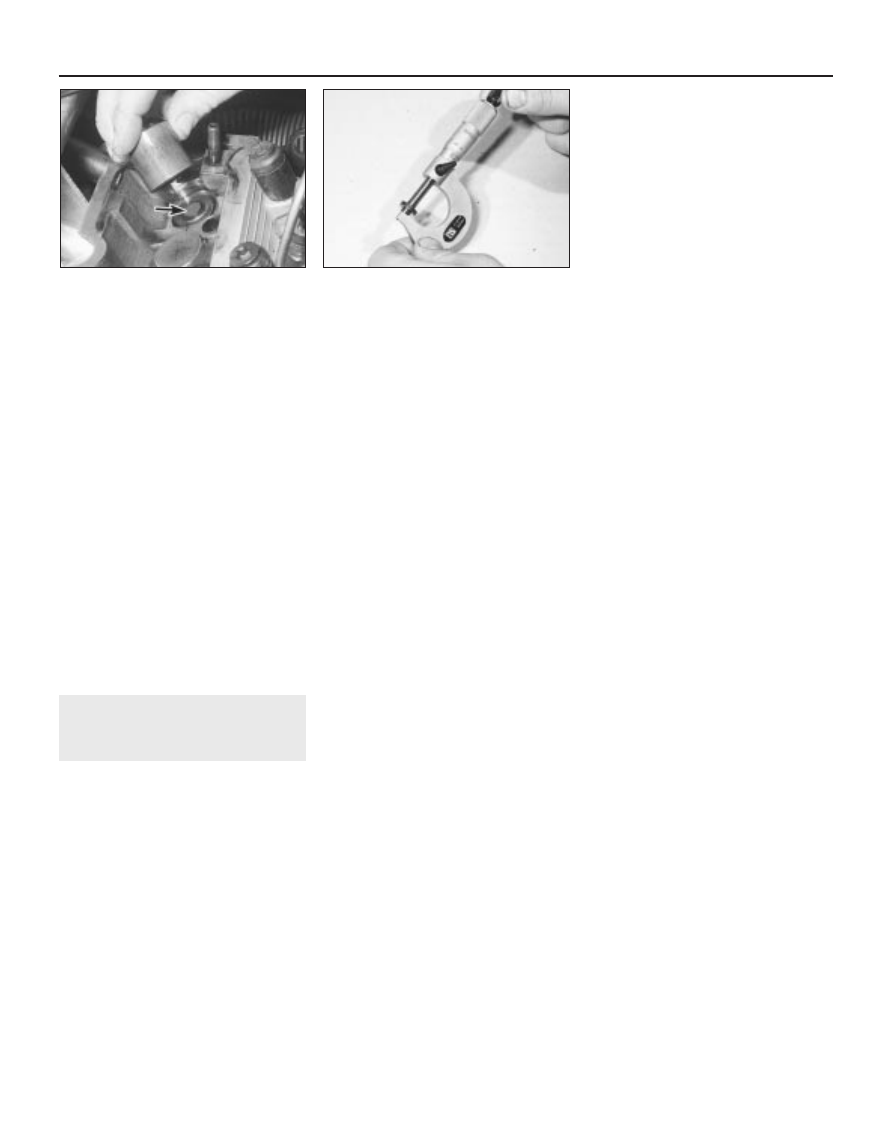
11.16a  Lift out the follower and remove

the shim (arrowed)

11.16b  Using a micrometer to measure

shim thickness

holes, and gently “rock” the cylinder head free
towards the front of the car (see Part A). On
wet liner engines, do not try to swivel the head
on the cylinder block/crankcase; it is located
by dowels, as well as by the tops of the liners.
20 When the joint is broken, lift the cylinder
head away. Seek assistance if possible, as it
is a heavy assembly, especially if it is
complete with the manifolds. Remove the
gasket from the top of the block, noting the
two locating dowels. If the locating dowels are
a loose fit, remove them and store them with
the head for safe-keeping. Do not discard the
gasket; it will be needed for identification
purposes.
21 On wet liner engines, do not attempt to
turn the crankshaft with the cylinder head
removed, otherwise the wet liners may be
displaced. Operations that require the
crankshaft to be turned (eg cleaning the
piston crowns), should only be carried out
once the cylinder liners are firmly clamped in
position. In the absence of the special
Peugeot liner clamps, the liners can be
clamped in position as follows. Use large flat
washers positioned underneath suitable-
length bolts, or temporarily refit the original
head bolts, with suitable spacers fitted to their
shanks (see illustration).
22 If the cylinder head is to be dismantled for
overhaul, remove the camshaft as described
in Section 10, then refer to Part C of this
Chapter.

1905 cc 16-valve engines

23 Remove the cylinder head cover as
described in Section 4. Also remove the air
cleaner inlet ducting.
24 Unbolt the plastic cover from over the
power steering pump drive pulley.
25 Disconnect the drivebelt from the power
steering drive pulley with reference to 
Chapter 1.
26 Unscrew the bolt and remove the pulley
from the end of the exhaust camshaft.
27 Identify all wiring connections on the
cylinder head then disconnect them. Also
disconnect the coolant hoses from the head.
28 Remove the ignition coil as described in
Chapter 5.
29 Remove the inlet manifold as described in
Chapter 4. To prevent damage to the radiator,
position a piece of cardboard over it. On

models with air conditioning, disconnect the
associated wiring from the inlet manifold.
30 Working as described in Chapter 4,
disconnect the exhaust system front pipe
from the manifold.
31 Place a jack beneath the engine, with a
block of wood on the jack head. Raise the
jack until it is supporting the weight of the
engine.
32 Remove the right-hand engine mounting
bracket with reference to Section 18.
33 Remove the timing belt as described in
Section 7.
34 Working in the reverse of the tightening
sequence, progressively slacken the ten
cylinder head bolts by half a turn at a time,
until all bolts can be unscrewed by hand.
Remove the bolts along with their washers,
noting the correct location of the spacer fitted
to the front left-hand bolt.
35 Release the end of the timing belt cover
from the coolant pump using a screwdriver.
36 With all the cylinder head bolts removed,
the joint between the cylinder head and
gasket and the cylinder block/crankcase must
now be broken without disturbing the wet
liners. Care must be taken to prevent
displacement of the wet liners. Although these
liners are better-located and sealed than
some wet-liner engines, there is still a risk of
coolant and foreign matter leaking into the
sump if the cylinder head is lifted carelessly. If
care is not taken and the liners are moved,
there is also a possibility of the bottom seals
being disturbed, causing leakage after
refitting the head.
37 To break the joint, obtain two L-shaped
metal bars which fit into the cylinder head bolt
holes, and gently “rock” the cylinder head free
towards the front of the car (see Part A). Do
not 
try to swivel the head on the cylinder
block/crankcase; it is located by dowels, as
well as by the tops of the liners. Take care not
to damage the oil supply tubes when inserting
the metal bars - if necessary remove the tubes
first.
38 When the joint is broken, lift the cylinder
head away. Seek assistance if possible, as it
is a heavy assembly. Remove the gasket from
the top of the block, noting the two locating
dowels. If the locating dowels are a loose fit,
remove them and store them with the head for
safe-keeping. Do not discard the gasket; it will
be needed for identification purposes.
39 Do not attempt to turn the crankshaft with
the cylinder head removed, otherwise the wet
liners may be displaced. Operations that
require the crankshaft to be turned (eg
cleaning the piston crowns), should only be
carried out once the cylinder liners are firmly
clamped in position. In the absence of the
special Peugeot liner clamps, the liners can
be clamped in position as follows. Use large
flat washers positioned underneath suitable-
length bolts, or temporarily refit the original
head bolts, with suitable spacers fitted to their
shanks.
40 If the cylinder head is to be dismantled for

overhaul, remove the camshafts as described
in Section 10, then refer to Part C of this
Chapter.

1998 cc 16-valve engines

41 The procedure is similar to that for the
1905 cc 16-valve engine described above,
except for the following.

a) Where necessary remove both camshafts

at the beginning of the procedure as
described in Section 10.

b) When removing the inlet manifold,

disconnect the ACAV assembly with
reference to Chapter 4.

c) Unbolt the oil dipstick tube from the

cylinder head.

d) The 1998 cc 16-valve engine has dry

liners, and therefore all references to, and
precautions for, wet liners can be ignored.

Preparation for refitting

42 The mating faces of the cylinder head and
cylinder block/crankcase must be perfectly
clean before refitting the head. Use a hard
plastic or wooden scraper to remove all traces
of gasket and carbon; also clean the piston
crowns. On ‘wet’ liner engines, refer to
paragraph 36 before turning the engine. Take
particular care on these models, as the soft
aluminium alloy is easily damaged. On all
models, make sure that the carbon is not
allowed to enter the oil and water passages -
this is particularly important for the lubrication
system, as carbon could block the oil supply
to the engine’s components. Using adhesive
tape and paper, seal the water, oil and bolt
holes in the cylinder block/crankcase. To
prevent carbon entering the gap between the
pistons and bores, smear a little grease in the
gap. After cleaning each piston, use a small
brush to remove all traces of grease and
carbon from the gap, then wipe away the
remainder with a clean rag. Clean all the
pistons in the same way.
43 Check the mating surfaces of the cylinder
block/crankcase and the cylinder head for
nicks, deep scratches and other damage. If
slight, they may be removed carefully with a
file, but if excessive, machining may be the
only alternative to renewal. If warpage of the
cylinder head gasket surface is suspected,
use a straight-edge to check it for distortion.
Refer to Part C of this Chapter if necessary.
44 On ‘wet’ liner engines, check the cylinder
liner protrusion as described in Part C of this
Chapter.

Cylinder head gasket and head bolt
information - 1580 cc, 1761 cc and
1905 cc models

45 On these models (aluminium cylinder
block, wet-liner type engine) when purchasing
a new cylinder head gasket, it is essential that
a gasket of the correct thickness is obtained.
There are two different thicknesses available,
the standard (1.2 mm) gasket which is fitted at
the factory, and a slightly thicker (1.4 mm)
gasket, for use once the head gasket face has
been machined. The two gaskets can be

XU engine in-car repair procedures  2B•19

2B

12.21  Cylinder liners clamped in position

using suitable bolts and large flat washers

identified as follows, by the holes in the tab on
the left-hand end of the gasket.
46 With the gasket fitted the correct way up
on the cylinder block, there will be a either a
single hole, or series of holes, punched in the
tab on the left-hand end of the gasket. The
standard (1.2 mm) gasket has only one hole
punched in it; the slightly thicker (1.4 mm)
gasket has either two or three holes punched
in it, depending on its manufacturer. Identify
the gasket type, and ensure that the new
gasket obtained is of the correct thickness. If
there is any doubt as to which gasket is fitted,
take the old gasket along to your Peugeot
dealer, and have the dealer confirm the gasket
type.
47 Check the condition of the cylinder head
bolts, and particularly their threads, whenever
they are removed. Wash the bolts in a suitable
solvent, and wipe them dry. Check each bolt
for any sign of visible wear or damage,
renewing them if necessary. Measure the
length of each bolt (without the washer fitted),
from the underside of its head to the end of
the bolt. If all bolts are less than 176.5 mm,
they may be re-used. However, if any one bolt
is longer than the specified length, all of the
bolts should be renewed as a complete set.
Considering the stress which the cylinder
head bolts are under, it is hightly
recommended that they are renewed,
regardless of their apparent condition.

Cylinder head gasket and head bolt
information - 1998 cc 8-valve and 
16-valve models

48 On 1998 cc models (cast-iron cylinder
block without separate liners) there is only one
thickness of head gasket available. The holes
described above are still punched into the
left-hand end of the gasket, but are of little
importance, as they only identify the gasket
manufacturer.
49 Check the condition of the cylinder head
bolts, and particularly their threads, whenever
they are removed. Wash the bolts in a suitable
solvent, and wipe them dry. Check each bolt
for any sign of visible wear or damage,
renewing them if necessary. Measure the
length of each bolt (without the washer fitted),
from the underside of its head to the end of
the bolt. If all bolts are less than 122.0 mm,
they may be re-used. However, if any one bolt
is longer than the specified length, all of the
bolts should be renewed as a complete set.
Considering the stress which the cylinder
head bolts are under, it is hightly
recommended that they are renewed,
regardless of their apparent condition.

Refitting

50 Wipe clean the mating surfaces of the
cylinder head and cylinder block/crankcase.
Check that the two locating dowels are in
position at each end of the cylinder
block/crankcase surface. Where applicable,
remove the cylinder liner clamps.
51 Position a new gasket on the cylinder

block/crankcase surface, ensuring that its
identification holes and tongue are at the left-
hand end of the gasket.

8-valve engines

52 Where removed refit the camshaft
(Section 10), then check that the crankshaft
pulley and camshaft sprocket are still locked
in position with their respective pins. With the
aid of an assistant, carefully refit the cylinder
head assembly to the block, aligning it with
the locating dowels.
53 Apply a smear of grease to the threads,
and to the underside of the heads, of the
cylinder head bolts. Peugeot recommend
Molykote G.RAPID PLUS grease (available
from your Peugeot dealer); in the absence of
the specified grease, any good-quality high-
melting-point grease may be used.
54 Carefully enter each bolt and washer into
its relevant hole (do not drop it in) and screw it
in finger-tight, not forgetting to fit the spacer
to the front left-hand bolt.
55 Working progressively and in the
sequence shown, tighten the cylinder head
bolts to their stage 1 torque setting, using a
torque wrench and suitable socket (see
illustration)
.
56 On 1508 cc, 1761 cc and 1905 cc
engines, working bolt by bolt and in the
specified sequence,  fully slacken the bolt
then tighten it to its stage 2 torque setting
followed by its stage 3 angle. It is
recommended that an angle-measuring
gauge is used during the stage 3 tightening, to
ensure accuracy. If a gauge is not available,
use white paint to make alignment marks
between the bolt head and cylinder head prior
to tightening; the marks can then be used to
check that the bolt has rotated sufficiently.
57 On 1998 cc engines, working in the
correct sequence tighten all of the bolts to 
the stage 2 torque. With all the bolts at the
stage 2 torque, angle-tighten the bolts to the
stage 3 angle in the correct sequence using
the gauge described in the previous
paragraph.
58 Once the cylinder head bolts are correctly
tightened, fill the four oil reservoir holes in the
cylinder head (below the camshaft) with fresh
engine oil.
59 Reconnect the wiring connector to the
ignition HT coil. Otherwise, if the head was

stripped for overhaul, refit the HT coil or
distributor (as applicable), as described in
Chapter 5.
60 Refit and tension the timing belt with
reference to Section 8.
61 Refit the right-hand engine mounting and
tighten the bolts to the specified torque. The
jack can then be removed from under the
engine.
62 The remaining procedure is a reversal of
removal noting the following points.

a) Ensure that all wiring is correctly routed,

and that all connectors are securely
reconnected to the correct components.

b) Ensure that the coolant hoses are

correctly reconnected, and that their
retaining clips are securely tightened.

c) Ensure that all vacuum/breather hoses are

correctly reconnected.

d) Refit the cylinder head cover as described

in Section 4.

e) Reconnect the exhaust system to the

manifold, refit the air cleaner housing and
ducts, and adjust the accelerator cable,
as described in Chapter 4. If the
manifolds were removed, refit these as
described in Chapter 4.

f) On completion, refill the cooling system

as described in Chapter 1, and reconnect
the battery.

1905 cc 16-valve engines

63 Where removed refit the camshafts
(Section 10), then check that the crankshaft
pulley and camshaft sprockets are still locked
in position with their respective pins. With the
aid of an assistant, carefully refit the cylinder
head assembly to the block, aligning it with
the locating dowels.
64 Apply a smear of grease to the threads,
and to the underside of the heads, of the
cylinder head bolts. Peugeot recommend the
use of Molykote G.RAPID PLUS grease
(available from your Peugeot dealer); in the
absence of the specified grease, any good-
quality high-melting-point grease may be
used.
65 Carefully enter each bolt and washer into
its relevant hole (do not drop it in) and screw it
in finger-tight, not forgetting to fit the spacer
to the front left-hand bolt.
66 Working progressively and in the
sequence shown, tighten the cylinder head
bolts to their stage 1 torque setting, using a
torque wrench and suitable socket.
67 Working bolt by bolt and in the specified
sequence,  fully slacken the bolt then tighten it
to its stage 2 torque setting followed by its
stage 3 angle. It is recommended that an
angle-measuring gauge is used during the
stage 3 tightening, to ensure accuracy. If a
gauge is not available, use white paint to
make alignment marks between the bolt head
and cylinder head prior to tightening; the
marks can then be used to check that the bolt
has rotated sufficiently.
68 Refit and tension the timing belt with
reference to Section 8.

2B•20 XU engine in-car repair procedures

12.55  Cylinder head bolt tightening

sequence

69 Refit the right-hand engine mounting and
tighten the bolts to the specified torque. The
jack can then be removed from under the
engine.
70 The remaining procedure is a reversal of
removal noting the following points.

a) Ensure that all wiring is correctly routed,

and that all connectors are securely
reconnected to the correct components.

b) Ensure that the coolant hoses are

correctly reconnected, and that their
retaining clips are securely tightened.

c) Ensure that all vacuum/breather hoses are

correctly reconnected.

d) Refit the cylinder head cover as described

in Section 4.

e) Reconnect the exhaust system to the

manifold, refit the air cleaner housing and
ducts, and refit the manifolds as
described in Chapter 4.

f) Reconnect the power steering drive pulley

and drivebelt with reference to Chapter 1.

g) On completion, refill the cooling system

as described in Chapter 1, and reconnect
the battery.

1998 cc 16-valve models

71 The procedure is similar to that for the
1905 cc 16-valve engine described above, but
refer also to paragraph 40.

13 Sump - removal and refitting

3

Removal

Disconnect the battery negative lead.
Drain the engine oil, then clean and refit the
engine oil drain plug, tightening it securely. If
the engine is nearing its service interval when
the oil and filter are due for renewal, it is
recommended that the filter is also removed,
and a new one fitted. After reassembly, the
engine can then be refilled with fresh oil. Refer
to Chapter 1 for further information.
Apply the handbrake, jack up the front of
the vehicle and support it on axle stands (see
“Jacking and Vehicle Support”).
On models with air conditioning, where the
compressor is mounted onto the side of the
sump, remove the drivebelt as described in
Chapter 1. Unbolt the compressor, and position
it clear of the sump. Support the weight of the
compressor by tying it to the vehicle, to prevent
any excess strain being placed on the
compressor lines. Do not disconnect the
refrigerant lines from the compressor (refer to
the warnings given in Chapter 3).
Where necessary, disconnect the wiring
connector from the oil temperature sender
unit, which is screwed into the sump.
Progressively slacken and remove all the
sump retaining bolts. Since the sump bolts
vary in length, remove each bolt in turn, and
store it in its correct fitted order by pushing it
through a clearly-marked cardboard template.

This will avoid the possibility of installing the
bolts in the wrong locations on refitting.
Break the joint by striking the sump with the
palm of your hand. Lower the sump, and
withdraw it from underneath the vehicle.
Remove the gasket (where fitted), and discard
it; a new one must be used on refitting.
While the sump is removed, take the
opportunity to check the oil pump pick-
up/strainer for signs of clogging or splitting. If
necessary, remove the pump as described in
Section 14, and clean or renew the strainer.
On some models fitted with the 1905 cc 
16-valve engine, a large spacer plate is fitted
between the sump and the base of the
cylinder block/crankcase. If this plate is fitted,
undo the two retaining screws from
diagonally-opposite corners of the plate.
Remove the plate from the base of the engine,
noting which way round it is fitted.

Refitting

10 Clean all traces of sealant/gasket from the
mating surfaces of the cylinder
block/crankcase and sump, then use a clean
rag to wipe out the sump and the engine’s
interior.
11 Where a spacer plate is fitted, remove all
traces of sealant/gasket from the spacer
plate, then apply a thin coating of suitable
sealant to the plate upper mating surface (see
illustrations)
. Offer up the plate to the base of
the cylinder block/crankcase, and securely
tighten its retaining screws.
12 On models where the sump was fitted
without a gasket (cast-aluminium sump),
ensure that the sump mating surfaces are
clean and dry, then apply a thin coating of
suitable silicone sealant to the sump mating
surface.
13 On models where the sump was fitted
with a gasket (pressed-steel sump), ensure
that all traces of the old gasket have been
removed, and that the sump mating surfaces
are clean and dry. Position the new gasket on
the top of the sump, using a dab of grease to
hold it in position.
14 Offer up the sump to the cylinder
block/crankcase. Refit its retaining bolts,
ensuring that each is screwed into its original
location. Tighten the bolts evenly and
progressively to the specified torque setting.

15 Where necessary, align the air
conditioning compressor with its mountings
on the sump, and insert the retaining bolts.
Securely tighten the compressor retaining
bolts, then refit the drivebelt as described in
Chapter 1.
16 Reconnect the wiring connector to the oil
temperature sensor (where fitted).
17 Lower the vehicle to the ground, then refill
the engine with oil as described in Chapter 1.

14 Oil pump - removal,

inspection and refitting

3

Removal

Remove the sump (see Section 13).
Where necessary, undo the two retaining
screws, and slide the sprocket cover off the
front of the oil pump.
Slacken and remove the three bolts
securing the oil pump to the base of the
cylinder block/crankcase. Disengage the
pump sprocket from the chain, and remove
the oil pump (see illustration). Where
necessary, also remove the spacer plate
which is fitted behind the oil pump.

Inspection

Examine the oil pump sprocket for signs of
damage and wear, such as chipped or
missing teeth. If the sprocket is worn, the
pump assembly must be renewed, since the
sprocket is not available separately. It is also
recommended that the chain and drive

XU engine in-car repair procedures  2B•21

14.3  Removing the oil pump

13.11b  . . . then refit the plate to the base

of the cylinder block/crankcase

13.11a  Where a sump spacer plate is

fitted, apply a coat of suitable sealant to

the plate upper surface . . .

2B


содержание   ..  17  18  19  20   ..