содержание .. 36 37 38 39 ..
Peugeot 205. Manual - part 38
3 If the hub nut has yet to be loosened,
fabricate a tool from two lengths of steel strip
(one long, one short) and a nut and bolt; the
nut and bolt form the pivot of a forked tool.
Bolt the tool to the hub flange using two wheel
bolts, and hold the tool to prevent the hub
from rotating (see Chapter 8, Section 2).
Slacken the hub nut using a socket and a long
extension bar.
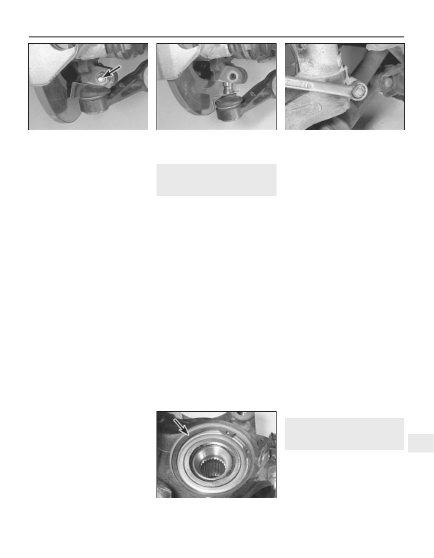
4 Unscrew the clamp bolt securing the front
suspension lower balljoint to the bottom of the
hub carrier then pull the lower suspension arm
down from the carrier (see illustrations).
5 Recover the balljoint guard plate, where
fitted.
6 Turn the front wheels to full right-hand lock
(left-hand hub carrier), or full left-hand lock
(right-hand hub carrier) and remove the hub
nut and, where fitted, the washer. Note that a
new hub nut will be required for refitting.
7 Pull the hub carrier outwards and at the
same time withdraw the outer end of the
driveshaft from the hub. Suitably support or
tie up the driveshaft in a near horizontal
position to avoid damage to the inner CV
joints.
8 Unbolt the disc brake caliper from the hub
carrier and either place it on a stand or tie it to
one side.
9 Remove the two screws and withdraw the
brake disc.
10 Unscrew the nut and use a balljoint
removal tool to separate the track rod end
balljoint from the hub carrier steering arm.
11 Unscrew the clamp bolt securing the
lower end of the suspension strut to the hub
carrier (see illustration). Spread the slot on
the hub carrier using a screwdriver or suitable
wedge and slide the carrier from the bottom
of the strut. Remove the hub carrier from the
car.
Refitting
12 Refitting is a reversal of removal, but refer
to Chapters 8 and 9 respectively when
refitting the driveshaft and disc brake caliper.
3
Front hub bearings - renewal
4
Note: The bearing is a sealed, pre-adjusted
and pre-lubricated, double-row ball type, and
is intended to last the car’s entire service life
without maintenance or attention. Never
overtighten the driveshaft nut beyond the
specified torque wrench setting in an attempt
to “adjust” the bearing.
Note: A press will be required to dismantle
and rebuild the assembly; if such a tool is not
available, a large bench vice and spacers
(such as large sockets) will serve as an
adequate substitute. The bearing’s inner races
are an interference fit on the hub; if the inner
race remains on the hub when it is pressed
out of the hub carrier, a knife-edged bearing
puller will be required to remove it. A new
bearing retaining circlip must be used on
refitting.
1 Remove the hub carrier assembly as
described in Section 2.
2 Support the hub carrier securely on blocks
or in a vice. Using a tubular spacer which
bears only on the inner end of the hub flange,
press the hub flange out of the bearing. If the
bearing’s outboard inner race remains on the
hub, remove it using a bearing puller (see note
above).
3 Extract the bearing retaining circlip from the
inner end of the hub carrier assembly (see
illustration).
4 Where necessary, refit the inner race back
in position over the ball cage, and securely
support the inner face of the hub carrier.
Using a tubular spacer which bears only on
the inner race, press the complete bearing
assembly out of the hub carrier.
5 Thoroughly clean the hub and hub carrier,
removing all traces of dirt and grease, and
polish away any burrs or raised edges which
might hinder reassembly. Check both for
cracks or any other signs of wear or damage,
and renew them if necessary. Renew the
circlip, regardless of its apparent condition.
6 On reassembly, apply a light film of oil to
the bearing outer race and hub flange shaft, to
aid installation of the bearing.
7 Securely support the hub carrier, and locate
the bearing in the hub. Press the bearing fully
into position, ensuring that it enters the hub
squarely, using a tubular spacer which bears
only on the bearing outer race.
8 Once the bearing is correctly seated,
secure the bearing in position with the new
circlip, ensuring that it is correctly located in
the groove in the hub carrier.
9 Securely support the outer face of the hub
flange, and locate the hub carrier bearing
inner race over the end of the hub flange.
Press the bearing onto the hub, using a
tubular spacer which bears only on the inner
race of the hub bearing, until it seats against
the hub shoulder. Check that the hub flange
rotates freely, and wipe off any excess oil or
grease.
10 Refit the hub carrier assembly as
described in Section 2.
4
Front suspension strut -
removal and refitting
4
Removal
1 Before raising the car it is recommended
that a retaining tool is fitted to the coil spring
to hold the spring in a semi-compressed
state. This will provide sufficient clearance to
enable the strut to be withdrawn from the hub
carrier. Peugeot garages use two special
cables inserted through the holes at the top of
Suspension and steering 10•3
10
2.4a Unscrew the lower balljoint clamp
bolt . . .
2.4b . . . and pull the suspension arm down
from the hub carrier
2.11 Unscrew the clamp bolt securing the
lower end of the suspension strut to the
hub carrier
3.3 Front hub bearing retaining circlip
(arrowed)