Peugeot 205. Manual - part 34


  Главная      Peugeot     Peugeot 205 - Service And Repair Manual Haynes


поиск по сайту            


содержание   ..  32  33  34  35   ..


Peugeot 205. Manual - part 34


Bleeding - basic (two-man)
method

13 Collect a clean glass jar of reasonable size
and a suitable length of plastic or rubber
tubing, which is a tight fit over the bleed
screw, and a ring spanner to fit the screws.
The help of an assistant will also be required.
14 If not already done, remove the dust cap
from the bleed screw of the first wheel to be
bled and fit the spanner and bleed tube to the
screw (see illustration). Place the other end
of the tube in the jar, and pour in sufficient
fluid to cover the end of the tube.
15 Ensure that the master cylinder reservoir
fluid level is maintained at least above the
“MIN” level line throughout the procedure.
16 Have the assistant fully depress the brake
pedal several times to build up pressure, then
maintain it on the final downstroke.
17 While pedal pressure is maintained,
unscrew the bleed screw (approximately one
turn) and allow the compressed fluid and air to
flow into the jar. The assistant should maintain
pedal pressure, following it down to the floor if
necessary, and should not release it until
instructed to do so. When the flow stops,
tighten the bleed screw again have the
assistant release the pedal slowly, and
recheck the reservoir fluid level.
18 Repeat the steps given in paragraphs 16
and 17 until the fluid emerging from the bleed
screw is free from air bubbles. If the master
cylinder has been drained and refilled, and air
is being bled from the first screw in the

sequence, allow approximately five seconds
between cycles for the master cylinder
passages to refill.
19 On 1.6 GTI models only it is now
important to dislodge air trapped in the inertia
compensator. To do this, open the bleed
screw again and have your assistant fully
depress and release the brake pedal rapidly 4
or 5 times, finally keeping the pedal
depressed before tightening the bleed screw.
20 When no more air bubbles appear, tighten
the bleed screw securely, remove the tube
and spanner and refit the dust cap. Do not
overtighten the bleed screw.
21 Repeat these procedures on the
remaining brakes in sequence until all air is
removed from the system and the brake pedal
feels firm again.

Bleeding - using a one-way
valve kit

22 As their name implies, these kits consist of
a length of tubing with a one-way valve fitted,
to prevent expelled air and fluid being drawn
back into the system; some kits include a
translucent container, which can be positioned
so that the air bubbles can be more easily
seen flowing from the end of the tube.
23 The kit is connected to the bleed screw,
which is then opened. The user returns to the
driver’s seat, depresses the brake pedal with
a smooth steady stroke, and slowly releases
it; this is repeated until the expelled fluid is
clear of air bubbles. When using one of these
kits on 1.6 GTI models, remember to carry out
the procedure described in paragraph 19 after
bleeding the first brake in the sequence.
24 Note that these kits simplify work so
much that it is easy to forget the master
cylinder fluid level; ensure that this is
maintained at least above the “MIN” level line
at all times.

Bleeding - using a pressure-
bleeding kit

25 These kits are usually operated by the
reserve of pressurised air contained in the
spare tyre. However, note that it will probably
be necessary to reduce the pressure to a
lower level than normal; refer to the
instructions supplied with the kit.
26 By connecting a pressurised, fluid-filled
container to the master cylinder reservoir,
bleeding is then carried out by simply opening
each bleed screw in turn (in the specified
sequence) and allowing the fluid to run out,
until no more air bubbles can be seen in the
expelled fluid. When using one of these kits
on 1.6 GTI models, remember to carry out the
procedure described in paragraph 19 after
bleeding the first brake in the sequence.
27 This method has the advantage that the
large reservoir of fluid provides an additional
safeguard against air being drawn into the
system during bleeding.
28 Pressure bleeding is particularly effective
when bleeding “difficult” systems, or when
bleeding the complete system at the time of
routine fluid renewal.

All methods

29 When bleeding is complete, and firm
pedal feel is restored, wash off any spilt fluid,
tighten the bleed screws securely, and refit
their dust caps.
30 Check the hydraulic fluid level in the master
cylinder reservoir and top-up if necessary.
31 Discard any hydraulic fluid that has been
bled from the system; it will not be fit for re-use.
32 Check the feel of the brake pedal. If it feels
at all spongy, air must still be present in the
system, and further bleeding is required.
Failure to bleed satisfactorily after a reasonable
repetition of the bleeding operations may be
due to worn master cylinder seals.
33 On models with ABS, reconnect the wiring
connectors to the regulator unit and
reconnect the battery.

Braking system  9•3

9

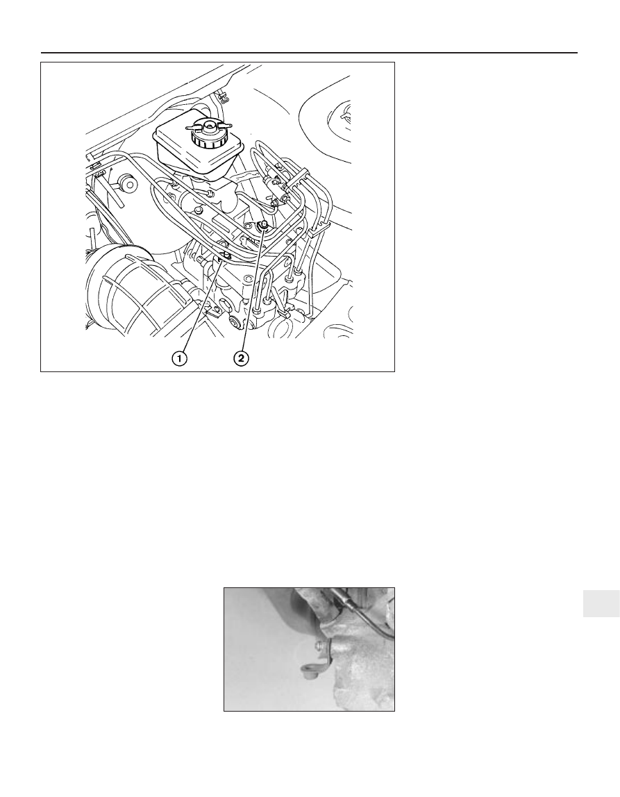
2.12  Bleed screws (1 and 2) on ABS regulator unit

2.14  Bleed screw and dust cap on front

brake caliper

3

Hydraulic pipes and hoses -
renewal

2

Note: Before starting work, refer to the
warning at the beginning of Section 2
concerning the dangers of hydraulic fluid
.
If any pipe or hose is to be renewed,
minimise hydraulic fluid loss by removing the
master cylinder reservoir cap, placing a piece
of plastic film over the reservoir and sealing it
with an elastic band. Alternatively, flexible
hoses can be sealed, if required, using a
proprietary brake hose clamp; metal brake
pipe unions can be plugged (if care is taken
not to allow dirt into the system) or capped
immediately they are disconnected. Place a
wad of rag under any union that is to be
disconnected, to catch any spilt fluid.
If a flexible hose is to be disconnected,
unscrew the brake pipe union nut before
removing the spring clip which secures the
hose to its mounting. Depending upon the
make of the particular caliper, the other end of
the hose may be connected simply by
screwing it into its tapped hole or by using a
hollow bolt with banjo end fitting. Use a new
copper sealing washer on each side of the
banjo union.
To unscrew the union nuts, it is preferable to
obtain a brake pipe spanner of the correct size;
these are available from most large motor
accessory shops. Failing this, a close-fitting
open-ended spanner will be required, though if
the nuts are tight or corroded, their flats may be
rounded-off if the spanner slips. In such a case,
a self-locking wrench is often the only way to
unscrew a stubborn union, but it follows that
the pipe and the damaged nuts must be
renewed on reassembly. Always clean a union
and surrounding area before disconnecting it. If
disconnecting a component with more than
one union, make a careful note of the
connections before disturbing any of them.
If a brake pipe is to be renewed, it can be
obtained, cut to length and with the union
nuts and end flares in place, from Peugeot
dealers. All that is then necessary is to bend it
to shape, following the line of the original,
before fitting it to the car. Alternatively, most
motor accessory shops can make up brake

pipes from kits, but this requires very careful
measurement of the original, to ensure that
the replacement is of the correct length. The
safest answer is usually to take the original to
the shop as a pattern.
Before refitting, blow through the new pipe
or hose with dry compressed air. Do not
overtighten the union nuts. It is not necessary
to exercise brute force to obtain a sound joint.
If flexible rubber hoses are renewed, ensure
that the pipes and hoses are correctly routed,
with no kinks or twists, and that they are
secured in the clips or brackets provided.
After fitting, bleed the hydraulic system as
described in Section 2, wash off any spilt
fluid, and check carefully for fluid leaks.

4

Front brake pads - renewal

2

Warning: Disc brake pads must
be renewed on both front
wheels at the same time - never
renew the pads on only one

wheel as uneven braking may result. Dust
created by wear of the pads may contain
asbestos, which is a health hazard. Never
blow it out with compressed air and do not
inhale any of it. DO NOT use petroleum-
based solvents to clean brake parts. Use
brake cleaner or methylated spirit only. DO
NOT allow any brake fluid, oil or grease to
contact the brake pads or disc. Also refer
to the warning at the start of Section 2
concerning the dangers of hydraulic fluid.

All models except 1.9 GTI

Chock the rear wheels then jack up the
front of the car and support it on axle stands
(see “Jacking and vehicle support”). Remove
the front roadwheels.
Note that two different types of brake
caliper may be fitted according to model and
year. Identify the type fitted, with reference to
the accompanying illustrations or the caliper
itself, then proceed as described under the
relevant sub-heading.

DBA Bendix caliper

Remove the clip from the end of the upper
sliding key. Disconnect the pad wear wiring
connector as necessary (see illustrations).
Pull out the upper sliding key (see
illustration)
.
Using a lever against the front suspension
strut, push the cylinder towards the brake disc
so that the outer pad can be withdrawn from
the caliper (see illustration).
Push back the caliper and withdraw the
inner pad (see illustration). Make a note of
the correct fitted position of the anti-rattle
springs and remove the spring from each pad.
Clean away all dust and dirt from the
caliper. Check for brake fluid leakage around
the piston dust seal and, if evident, overhaul
the caliper, as described later in this Chapter.
Check the brake disc for wear and also check
that the rubber bellows on the cylinder sliding
rods are in good condition.
Clean the backs of the brake pads and
apply a little anti-squeal brake grease. Also
apply the grease to the lower pad locating lip
of the caliper.

9•4 Braking system

4.3a  Pad sliding key clip - arrowed 

(DBA Bendix caliper)

4.3b  Disconnecting the pad wear wiring

connector (DBA Bendix caliper)

4.4  Removing the pad sliding key 

(DBA Bendix caliper)

4.5  Removing the outer pad 

(DBA Bendix caliper)

4.6  Removing the inner pad 

(DBA Bendix caliper)

With the caliper pushed inwards, insert the
inner pad then push the caliper outwards and
insert the outer pad. If offset pads are fitted, it
is important to fit these pads in the correct
positions as shown (see illustration). The
inner pads with pad wear wires must be
located at the top of the caliper.
10 Check that the pads are correctly
positioned on the caliper lip and with the anti-
rattle springs in place (see illustration) then
tap in the upper sliding key to lock them. Fit
the sliding key clip.

Girling caliper

11 Extract the spring clips and tap out the
pad retaining pins. Disconnect the pad wear
wiring as necessary (see illustration).
12 Lever the cylinder outwards and withdraw
the outer pad then push in the caliper and
withdraw the inner pad. Recover the anti-
squeal shims (if fitted) noting their positioning
with regards to the pad retaining pins - refer
to paragraph 14.
13 Clean and check the caliper, as described
in paragraph 7, then clean the backs of the

pads and apply a little anti-squeal brake
grease. Note that, as from early 1985, a
special spring is fitted to the inner pads to
prevent pad knock within the caliper. The
spring (obtainable from Peugeot dealers) may
be fitted to earlier models by tapping the inner
pad control rivet through the backing plate so
that the clip may be located on both sides
(see illustration).
14 With the caliper pushed inwards, insert
the inner pad then push the caliper outwards
and insert the outer pad. Note that from
chassis no 5 600 000, an anti-squeal shim
was fitted between the inner pads and the
caliper pistons, being located on both upper
and lower pad retaining pins. However, as

from chassis no 5 957 000, the shim was
modified, being located only on the lower pad
retaining pin (see illustrations). When fitting
the anti-squeal shims, the arrow cut-out must
face downwards (ie in the forward rotational
direction of the disc).
15 Tap in the pad retaining pins and fit the
spring clips.
16 Where fitted, hook the anti-knock spring
on the lower pad retaining pin.

1.9 GTI models

17 Chock the rear wheels then jack up the
front of the car and support it on axle stands
(see “Jacking and vehicle support”). Remove
the front roadwheels.

Braking system  9•5

9

4.11  Girling brake caliper and pad

arrangement

4.9  Correct orientation of offset brake pads viewed from front of

vehicle (DBA Bendix caliper)

4.10  Fitted position of the anti-rattle springs on the brake pads

(DBA Bendix caliper)

4.13  Method of fitting anti-knock spring to

Girling inner brake pad

1 Loop for rivet
2 Loop for lower retaining pin
3 Anti-knock spring

18 Disconnect the wire for the pad wear
warning light.
19 Hold the lower guide stationary with one
spanner, then unscrew the bolt (see
illustration)
.
20 Swivel the caliper upwards, then withdraw
the two brake pads from the caliper bracket
(see illustrations).
21 Clean and check the caliper, as described
in paragraph 7.
22 Push the piston fully into the cylinder.
23 Clean the backs of the pads, and apply a
little anti-squeal brake grease. Refit the inner
pad (with the pad wear warning wire), then the
outer pad.
24 Lower the caliper. Apply locking fluid to
the lower guide bolt, insert it, and tighten to
the specified torque while holding the guide
stationary with another spanner.
25 Reconnect the pad wear warning light
wire.

All calipers

26 Repeat the operations on the opposite
disc caliper.
27 Apply the footbrake several times to
position the pads against the discs.
28 Top-up the master cylinder reservoir to its
correct level.

29 Refit the roadwheels and lower the car to
the ground.
30 Note that if genuine Peugeot
replacements have been fitted, these pads
have a thin coating of abrasive material, which
cleans the disc during the initial applications
of the brakes. This coating also removes any
disc imperfections which would cause
steering vibration. After fitting these pads, the
brakes must be applied lightly and
intermittently for the first 3 miles (5 km), then
“bedded-in” for 120 miles (200 km), avoiding
heavy or prolonged braking wherever
possible.

5

Rear brake shoes - renewal

3

Warning: Brake shoes must be
renewed on both rear wheels at
the same time - never renew the
shoes on only one wheel, as

uneven braking may result. Also, the dust
created by wear of the shoes may contain
asbestos, which is a health hazard. Never
blow it out with compressed air, and don’t
inhale any of it. An approved filtering mask
should be worn when working on the

brakes. DO NOT use petrol or petroleum-
based solvents to clean brake parts; use
brake cleaner or methylated spirit only.
Note: The rear brake shoe assemblies may be
of either DBA Bendix or Girling manufacture,
according to model and year. The components
may vary in detail, but the principles described
in the following paragraphs are equally
applicable to both types. Make a careful note
of the fitted positions of all components before
dismantling.
Remove the relevant hub/drum as
described in Section 11.
Brush the dust and dirt from the shoes,
backplate and drum.
Note the position of each shoe and the
location of the return and steady springs (see
illustrations)
.
Unhook and remove the upper return spring
(see illustration).
Remove the steady springs using pliers to
depress the outer cups and turn them through
90° (see illustration). Remove the pins from
the backplate.
Move the serrated automatic adjuster lever
quadrant against spring tension (see
illustration)
, move the lever forwards and
release the strut from the top of the shoes
(DBA Bendix type only).

9•6 Braking system

4.14a  Early type anti-squeal shim 

(Girling caliper)

4.14b  Later type anti-squeal shim  

(Girling caliper)

4.19  Unscrewing the lower caliper guide

pin bolt (1.9 GTI)

4.20a  Swivel the caliper upwards . . .

4.20b . . . then withdraw the two brake pads (1.9 GTI)


содержание   ..  32  33  34  35   ..