содержание .. 28 29 30 31 ..
Peugeot 205. Manual - part 30
4
Air inlet heating system
components - removal and
refitting
2
Note: The components of the system vary
slightly according to engine type. The
following procedures depict one of the more
common systems, but all are similar.
Vacuum switch
Removal
1 Remove the air cleaner housing-to-
carburettor inlet duct.
2 Bend up the tangs on the switch retaining
clip, then remove the clip, along with its seal,
and withdraw the switch from inside the duct.
Examine the seal for signs of damage or
deterioration, and renew if necessary.
Refitting
3 On refitting, ensure that the switch and duct
mating surfaces are clean and dry, and
position the switch inside the duct.
4 Fit the seal over the switch unions, and refit
the retaining clip. Ensure that the switch is
pressed firmly against the duct, and secure it
in position by bending down the retaining clip
tangs. Refit the duct.
Air temperature control valve
Removal
5 Disconnect the vacuum pipe from the air
temperature control valve, then slacken the
retaining clips securing the inlet ducts to the
valve.
6 Disconnect both inlet ducts and the hot-air
inlet hose from the control valve assembly,
and remove it from the vehicle.
Refitting
7 Refitting is the reverse of the removal
procedure, noting that the air temperature
control valve assembly can only be renewed
as a complete unit.
5
Crankcase ventilation
system components -
removal and refitting
2
The crankcase ventilation system consists
simply of a number of ventilation hoses, and a
wire mesh filter in the engine oil filler cap on
certain models. Removal and refitting is self-
explanatory, but it may be necessary to
detach surrounding components for improved
access. Refer to the various Chapters of this
manual as necessary if problems are
encountered.
6
Electro-pneumatic ignition
retarding system components
- removal and refitting
2
Solenoid valve
Removal
1 The valve is located on a bracket at the rear
of the engine compartment. To remove the
valve, proceed as follows.
2 Disconnect the battery negative lead, then
disconnect the wiring plug from the valve (see
illustration).
3 Note the orientation of the valve, then
disconnect the hoses from the valve, and pull
the valve from its bracket.
Refitting
4 Refitting is a reversal of removal, ensuring
that the valve is correctly orientated, as noted
before removal.
Coolant temperature sensor
Removal
5 The sensor is located in the left-hand end of
the cylinder head, below the engine coolant
temperature sensor for the fuel injection
system.
6 To remove the sensor, partially drain the
cooling system (see Chapter 1), then
disconnect the wiring, and unscrew and
remove the sensor.
Refitting
7 When refitting the sensor, ensure that the
seal is in good condition, and take care not to
overtighten the switch. Refill the cooling
system on completion as described in
Chapter 1 and “Weekly checks”.
7
Catalytic converter - general
information and precautions
The catalytic converter is a reliable and
simple device, which needs no maintenance
in itself, but there are some facts of which an
owner should be aware if the converter is to
function properly for its full service life.
a) DO NOT use leaded petrol in a vehicle
equipped with a catalytic converter - the
lead will coat the precious metals,
reducing their converting efficiency, and
will eventually destroy the converter.
b) Always keep the ignition and fuel systems
well-maintained in accordance with the
manufacturer’s schedule (see Chapter 1).
c) If the engine develops a misfire, do not
drive the vehicle at all (or at least as little
as possible) until the fault is cured.
d) DO NOT push - or tow-start the vehicle -
this will soak the catalytic converter in
unburned fuel, causing it to overheat
when the engine does start.
e) DO NOT switch off the ignition at high
engine speeds, ie do not “blip” the
throttle immediately before switching off.
f) DO NOT use fuel or engine oil additives -
these may contain substances harmful to
the catalytic converter.
g) DO NOT continue to use the vehicle if the
engine burns oil to the extent of leaving a
visible trail of blue smoke.
h) Remember that the catalytic converter
operates at very high temperatures. DO
NOT, therefore, park the vehicle in dry
undergrowth, over long grass or piles of
dead leaves, after a long run.
I) Remember that the catalytic converter is
FRAGILE. Do not strike it with tools
during servicing work.
j) In some cases, a sulphurous smell (like
that of rotten eggs) may be noticed from
the exhaust. This is common to many
catalytic converter-equipped vehicles.
Once the vehicle has covered a few
thousand miles, the problem should
disappear - in the meantime, try changing
the brand of petrol used.
k) The catalytic converter used on a well-
maintained and well-driven vehicle should
last for between 50 000 and 100 000
miles. If the converter is no longer
effective, it must be renewed.
8
Fuel vapour recirculation
system components -
removal and refitting
2
Carbon canister
Removal
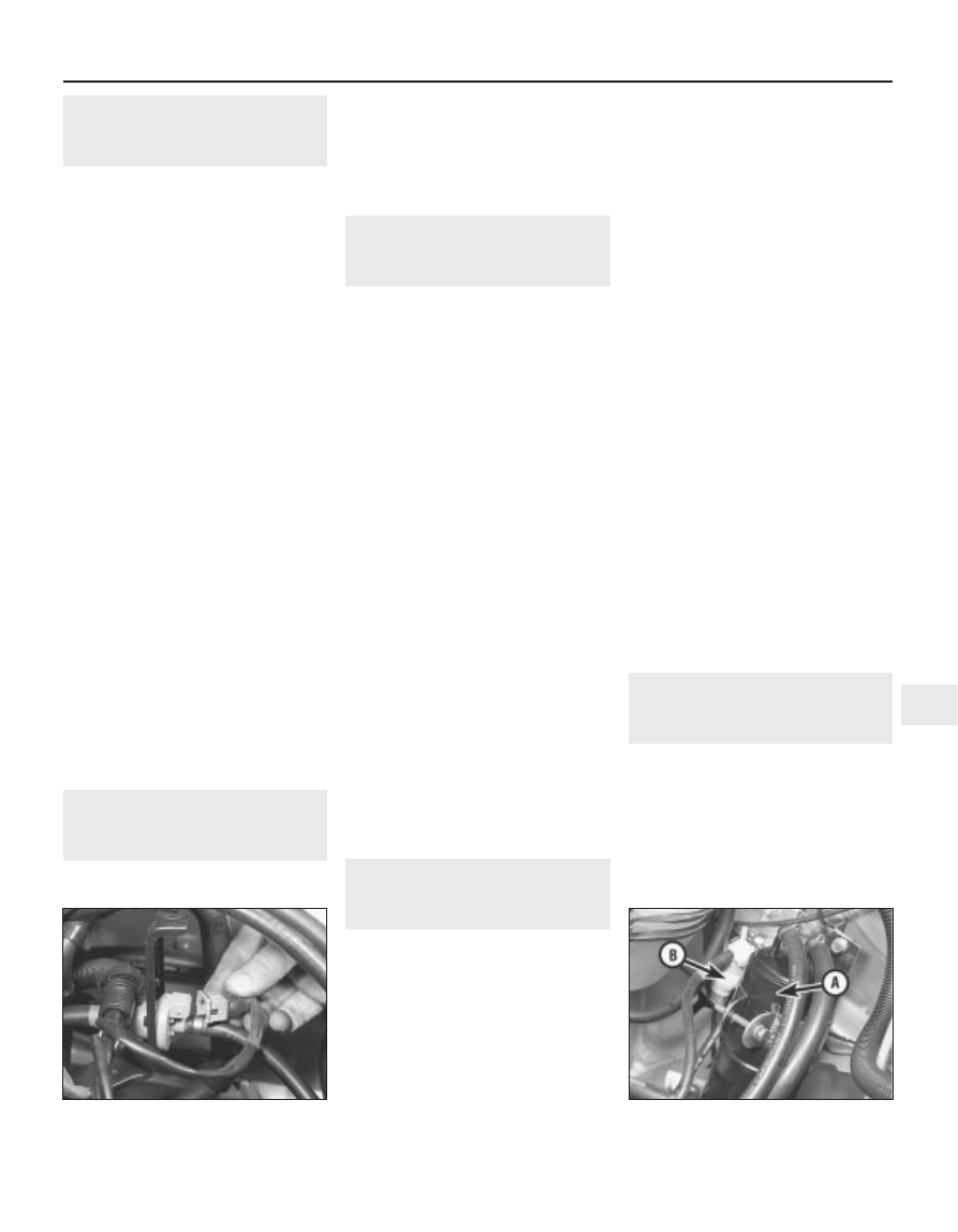
1 The carbon canister is located at the rear
left-hand corner of the engine compartment
(see illustration).
2 To remove the canister, first disconnect the
hoses, noting their locations to ensure correct
refitting.
Exhaust and emission control systems 4D•5
4D
6.2 Disconnecting wiring plug from
ignition retarding system solenoid valve
8.1 Fuel vapour recirculation system
carbon canister (A) and solenoid valve (B)