содержание .. 17 18 19 20 ..
Peugeot 205. Manual - part 19
XU series engines
3 On some early engines, both the upper and
lower bearing shells were of the same
thickness.
4 However, on later engines the main bearing
running clearance was significantly reduced.
To enable this to be done, four different grades
of bearing shell were introduced. The grades
are indicated by a colour-coding marked on the
edge of each shell, which denotes the shell’s
thickness, as listed in the following table. The
upper shell on all bearings is of the same size,
and the running clearance is controlled by
fitting a lower bearing shell of the required
thickness. This arrangement has been fitted to
all engines produced since mid-1994 and, if
possible, should also be fitted to earlier
engines during overhaul (see paragraph 11).
Bearing colour
Thickness (mm)
code
Standard
Undersize
Upper bearing:
Yellow
1.856
2.006
Lower bearing:
Blue (Class A)
1.836
1.986
Black (Class B)
1.848
1.998
Green (Class C)
1.859
2.009
Red (Class D)
1.870
2.020
Note: On later engines, upper shells are easily
distinguished from lower shells, by their
grooved bearing surface; the lower shells have
a plain surface.
5 On early engines, the correct size of bearing
shell must be selected by measuring the
running clearance as described under the
sub-heading below.
6 On engines produced since mid-1994,
when the new bearing shell sizes were
introduced, the crankshaft and cylinder
block/crankcase have had reference marks on
them to identify the size of the journals and
bearing bores.
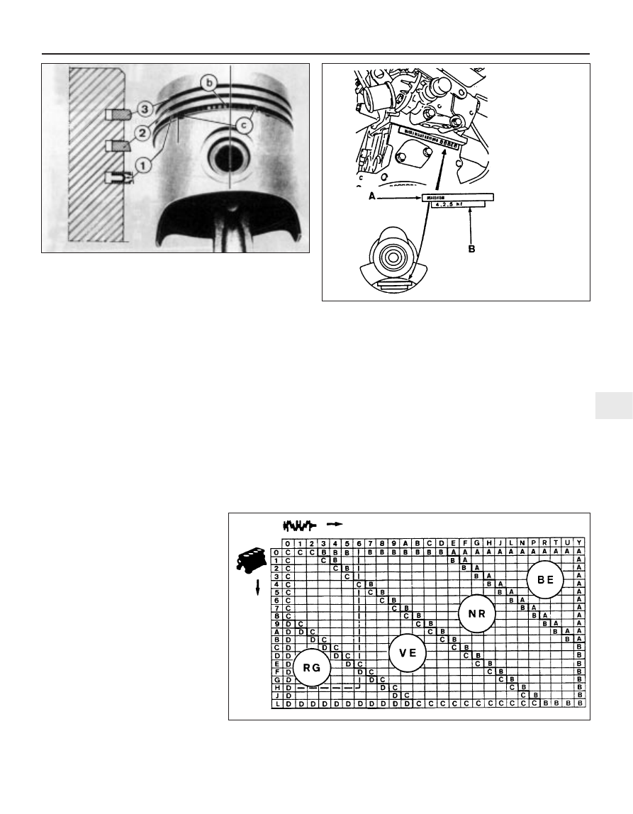
7 The cylinder block reference marks are on
the left-hand (transmission) end of the block.
The crankshaft reference marks are on the
left-hand (transmission) end of the crankshaft,
on the left-hand web of No 1 crankpin (see
illustration). These marks can be used to
select bearing shells of the required thickness
as follows.
8 On both the crankshaft and block, there
are two lines of identification, a bar code,
which is used by Peugeot during production,
and a row of five characters (letters and
numbers). The first character in the sequence
refers to the relevant size of No 1 bearing (at
the flywheel/driveplate end) and the last letter
in the sequence refers to the relevant size of
No 5 main bearing. These marks can be used
to select the required bearing shell grade as
follows.
9 Obtain the identification character of both
the relevant crankshaft journal and the
cylinder block bearing bore. Note that the
crankshaft characters are listed across the
top of the chart, and the cylinder block
characters down the side (see illustration).
Trace a vertical line down from the relevant
crankshaft character, and a horizontal line
across from the relevant cylinder block
character, and find the point at which both
lines cross. This crossover point will indicate
the grade of lower bearing shell required to
give the correct main bearing running
clearance. For example, the illustration shows
cylinder block reference H, and crankshaft
reference 6, crossing at a point within the area
of Class D, indicating that a Red (Class D)
lower bearing shell is required to give the
correct main bearing running clearance.
Engine removal and overhaul procedures 2D•17
2D
12.10 Piston ring identification
1 Oil control ring
2 Second compression ring
3 First compression ring
b Oil control expander ring
gap
c Oil control scraper ring gaps
13.7 Cylinder block
and crankshaft main
bearing reference
markings - later XU
series engines
A Bar code (used in
production)
B Identification characters
13.9 Main bearing shell selection chart - later XU series engines
BE Blue (Class A)
NR Black (Class B)
VE Green (Class C)
RG Red (Class D)