Peugeot 205. Manual - part 17


  Главная      Peugeot     Peugeot 205 - Service And Repair Manual Haynes


поиск по сайту            


содержание   ..  15  16  17  18   ..


Peugeot 205. Manual - part 1
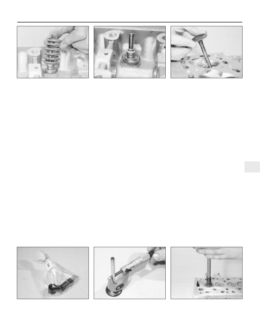
7


It is essential that each valve is stored
together with its collets, retainer, spring, and
spring seat. The valves should also be kept in
their correct sequence, unless they are so badly
worn that they are to be renewed. If they are
going to be kept and used again, place each
valve assembly in a labelled polythene bag or
similar small container (see illustration). Note
that No 1 valve is nearest to the transmission
(flywheel/driveplate) end of the engine.

Cleaning

Thoroughly clean all traces of old gasket
material and sealing compound from the
cylinder head upper and lower mating
surfaces. Use a suitable cleaning agent
together with a soft putty knife; do not use a
metal scraper or the faces will be damaged.
Remove the carbon from the combustion
chambers and ports, then clean all traces of
oil and other deposits from the cylinder head,
paying particular attention to the bearing
journals, cam follower bores (where
applicable), valve guides and oilways.
10 Wash the head thoroughly with paraffin or
a suitable solvent. Take plenty of time and do
a thorough job. Be sure to clean all oil holes
and galleries very thoroughly, dry the head
completely and coat all machined surfaces
with light oil.
11 Scrape off any heavy carbon deposits that
may have formed on the valves, then use a
power-operated wire brush to remove
deposits from the valve heads and stems.

Inspection

Note: Be sure to perform all the following
inspection procedures before concluding that

the services of an engineering works are
required. Make a list of all items that require
attention.

Cylinder head

12 Inspect the head very carefully for cracks,
evidence of coolant leakage, and other
damage. If cracks are found, a new cylinder
head should be obtained.
13 Use a straight-edge and feeler blade to
check that the cylinder head gasket surface is
not distorted. If it is, it may be possible to
have it machined. Seek the advice of a
Peugeot dealer or engine overhaul specialist if
distortion is suspected.
14 Examine the valve seats in each of the
combustion chambers. If they are severely
pitted, cracked, or burned, they will need to
be renewed or re-cut by an engine overhaul
specialist. If they are only slightly pitted, this
can be removed by grinding-in the valve
heads and seats with fine valve-grinding
compound, as described below.
15 Check the valve guides for wear by
inserting the relevant valve, and checking for
side-to-side motion of the valve. A very small
amount of movement is acceptable. If the
movement seems excessive, remove the valve.
Measure the valve stem diameter (see below),
and renew the valve if it is worn. If the valve
stem is not worn, the wear must be in the valve
guide, and the guide must be renewed. The
renewal of valve guides is best carried out by a
Peugeot dealer or engine overhaul specialist,
who will have the necessary tools available.
16 If renewing the valve guides, the valve
seats should be re-cut or re-ground only after
the guides have been fitted.

Valves

17 Examine the head of each valve for pitting,
burning, cracks, and general wear. Check the
valve stem for scoring and wear ridges. Rotate
the valve, and check for any obvious indication
that it is bent. Look for pits or excessive wear
on the tip of each valve stem. Renew any valve
that shows any such signs of wear or damage.
18 If the valve appears satisfactory at this
stage, measure the valve stem diameter at
several points using a micrometer (see
illustration)
. Any significant difference in the
readings obtained indicates wear of the valve
stem. Should any of these conditions be
apparent, the valve(s) must be renewed.
19 If the valves are in satisfactory condition,
they should be ground (lapped) into their
respective seats, to ensure a smooth, gas-
tight seal. If the seat is only lightly pitted, or if
it has been re-cut, fine grinding compound
only should be used to produce the required
finish. Coarse valve-grinding compound
should not be used, unless a seat is badly
burned or deeply pitted. If this is the case, the
cylinder head and valves should be inspected
by an expert, to decide whether seat re-
cutting, or even the renewal of the valve or
seat insert (where possible) is required.
20 Valve grinding is carried out as follows.
Place the cylinder head upside-down on a
bench.
21 Smear a trace of (the appropriate grade
of) valve-grinding compound on the seat face,
and press a suction grinding tool onto the
valve head (see illustration). With a semi-
rotary action, grind the valve head to its seat,

Engine removal and overhaul procedures  2D•9

2D

6.4c  . . . spring . . .

6.4d  . . . spring seat and valve stem oil

seal

6.6  Withdraw the valve through the

combustion chamber

6.7  Place each valve and its associated

components in a labelled polythene bag

6.18  Measuring the valve stem diameter

6.21  Grinding-in a valve

lifting the valve occasionally to redistribute the
grinding compound. A light spring placed
under the valve head will greatly ease this
operation.
22 If coarse grinding compound is being
used, work only until a dull, matt even surface
is produced on both the valve seat and the
valve, then wipe off the used compound, and
repeat the process with fine compound. When
a smooth unbroken ring of light grey matt
finish is produced on both the valve and seat,
the grinding operation is complete. Do not
grind-in the valves any further than absolutely
necessary, or the seat will be prematurely
sunk into the cylinder head.
23 When all the valves have been ground-in,
carefully wash off all traces of grinding
compound using paraffin or a suitable solvent,
before reassembling the cylinder head.

Valve components

24 Examine the valve springs for signs of
damage and discoloration. No minimum free
length is specified by Peugeot, so the only
way of judging valve spring wear is by
comparison with a new component.
25 Stand each spring on a flat surface, and
check it for squareness. If any of the springs
are damaged, distorted or have lost their
tension, obtain a complete new set of springs.
It is normal to renew the valve springs as a
matter of course if a major overhaul is being
carried out.
26 Renew the valve stem oil seals regardless
of their apparent condition.

Reassembly

27 Lubricate the stems of the valves, and
insert the valves into their original locations
(see illustration). If new valves are being
fitted, insert them into the locations to which
they have been ground.
28 Refit the spring seat then, working on the
first valve, dip the new valve stem seal in fresh
engine oil. Carefully locate it over the valve
and onto the guide. Take care not to damage
the seal as it is passed over the valve stem.
Use a suitable socket or metal tube to press
the seal firmly onto the guide (see
illustration)
.
29 Locate the valve spring on top of its seat,
then refit the spring retainer.

30 Compress the valve spring, and locate the
split collets in the recess in the valve stem.
Release the compressor, then repeat the
procedure on the remaining valves. 

31 With all the valves installed, place the
cylinder head face down on blocks on the
bench and, using a hammer and interposed
block of wood, tap the end of each valve stem
to settle the components.
32 Refit the camshaft, followers and shims
(as applicable) as described in Part A, B or C
of this Chapter.
33 The cylinder head can then be refitted as
described in Part A, B or C of this Chapter.

7

Piston/connecting rod
assembly - 
removal and
inspection

4

Removal

XV, XW and XY series engines

With the cylinder head removed, unscrew
and remove the bolts which hold the
crankcase half sections together. Split the
crankcase and keep the main bearing shells
with their crankcase web recesses if the shells
are to be used again (see illustration).

Remove the crankshaft oil seal.
Mark the rim of the cylinder liners in respect
of their position and orientation in the block.
Note that No 1 cylinder liner is at the
transmission (flywheel) end of the engine.
Mark the big-end caps and the connecting
rods so that they can be refitted in their
original sequence and the correct way round.
A centre punch or hacksaw blade is useful for
this purpose.
Unscrew the big-end nuts and remove the
caps (see illustration). If the bearing shells
are to be used again, keep them taped to their
respective cap.
Using a hammer handle, push the piston up
through the bore, and remove it from the top
of the cylinder liner. Recover the bearing shell,
and tape it to the connecting rod for safe-
keeping.
Loosely refit the big-end cap to the
connecting rod, and secure with the nuts -
this will help to keep the components in their
correct order.

XU and TU series engines

Remove the cylinder head, sump and oil
pump as described in Part B or C of this
Chapter (as applicable).
Using a hammer and centre-punch, paint or
similar, mark each connecting rod and big-
end bearing cap with its respective cylinder
number on the flat machined surface
provided; if the engine has been dismantled
before, note carefully any identifying marks
made previously (see illustration). Note that
No 1 cylinder is at the transmission (flywheel)
end of the engine.

2D•10 Engine removal and overhaul procedures

6.27  Lubricate the valve stems prior to

refitting

6.28  Fitting a valve stem oil seal using a

socket

7.1  Undo the bolts and split the crankcase

half sections - XV, XW and XY series engines

7.5  Remove the big-end bearing caps

7.9  Marks made on connecting rod and
bearing cap - XU and TU series engines

Use a little dab of grease to
hold the collets in position on
the valve stem while the
spring compressor is released.

10 Turn the crankshaft to bring pistons 1 and
4 to BDC (bottom dead centre).
11 Unscrew the nuts from No 1 piston big-
end bearing cap. Take off the cap, and
recover the bottom half bearing shell (see
illustration)
. If the bearing shells are to be re-
used, tape the cap and the shell together.
12 To prevent the possibility of damage to
the crankshaft bearing journals, tape over the
connecting rod stud threads.
13 Using a hammer handle, push the piston
up through the bore, and remove it from the
top of the cylinder block/liner. Recover the
bearing shell, and tape it to the connecting
rod for safe-keeping.
14 Loosely refit the big-end cap to the
connecting rod, and secure with the nuts -
this will help to keep the components in their
correct order.
15 Remove No 4 piston assembly in the
same way.
16 Turn the crankshaft through 180° to bring
pistons 2 and 3 to BDC (bottom dead centre),
and remove them in the same way.

Inspection

17 Before the inspection process can begin,
the piston/connecting rod assemblies must
be cleaned, and the original piston rings
removed from the pistons.
18 Carefully expand the old rings over the
top of the pistons. The use of two or three old
feeler blades will be helpful in preventing the
rings dropping into empty grooves (see
illustration)
. Be careful not to scratch the
piston with the ends of the ring. The rings are
brittle, and will snap if they are spread too far.
They are also very sharp - protect your hands
and fingers. Note that the third ring may
incorporate an expander. Always remove the
rings from the top of the piston. Keep each set
of rings with its piston if the old rings are to be
re-used.
19 Scrape away all traces of carbon from the
top of the piston. A hand-held wire brush (or a
piece of fine emery cloth) can be used, once
the majority of the deposits have been
scraped away.
20 Remove the carbon from the ring grooves
in the piston, using an old ring. Break the ring
in half to do this (be careful not to cut your
fingers - piston rings are sharp). Be careful to
remove only the carbon deposits - do not
remove any metal, and do not nick or scratch
the sides of the ring grooves.
21 Once the deposits have been removed,
clean the piston/connecting rod assembly
with paraffin or a suitable solvent, and dry
thoroughly. Make sure that the oil return holes
in the ring grooves are clear.
22 If the pistons and cylinder liners/bores are
not damaged or worn excessively, the original
pistons can be refitted. Normal piston wear
shows up as even vertical wear on the piston
thrust surfaces, and slight looseness of the
top ring in its groove. New piston rings should
always be used when the engine is
reassembled.

23 Carefully inspect each piston for cracks
around the skirt, around the gudgeon pin
holes, and at the piston ring “lands” (between
the ring grooves).
24 Look for scoring and scuffing on the
piston skirt, holes in the piston crown, and
burned areas at the edge of the crown. If the
skirt is scored or scuffed, the engine may
have been suffering from overheating, and/or
abnormal combustion which caused
excessively high operating temperatures. The
cooling and lubrication systems should be
checked thoroughly. Scorch marks on the
sides of the pistons show that blow-by has
occurred. A hole in the piston crown, or
burned areas at the edge of the piston crown,
indicates that abnormal combustion (pre-
ignition, knocking, or detonation) has been
occurring. If any of the above problems exist,
the causes must be investigated and
corrected, or the damage will occur again.
The causes may include incorrect ignition
timing, or a carburettor or fuel injection
system fault.
25 Corrosion of the piston, in the form of
pitting, indicates that coolant has been
leaking into the combustion chamber and/or
the crankcase. Again, the cause must be
corrected, or the problem may persist in the
rebuilt engine.
26 On aluminium-block engines with wet
liners, it is not possible to renew the pistons
separately; pistons are only supplied with
piston rings and a liner, as part of a matched
assembly (see Section 9). On cast-iron block
engines, pistons can be purchased from a
Peugeot dealer.
27 Examine each connecting rod carefully for
signs of damage, such as cracks around the
big-end and small-end bearings. Check that
the rod is not bent or distorted. Damage is
highly unlikely, unless the engine has been
seized or badly overheated. Detailed checking
of the connecting rod assembly can only be
carried out by a Peugeot dealer or engine
repair specialist with the necessary
equipment.
28 On XU series engines, due to the
tightening procedure for the connecting rod
big-end cap retaining nuts, it is highly
recommended that the big-end cap nuts and
bolts are renewed as a complete set prior to
refitting.

29 On all engines, the gudgeon pins are an
interference fit in the connecting rod small-
end bearing. Therefore, piston and/or
connecting rod renewal should be entrusted
to a Peugeot dealer or engine repair
specialist, who will have the necessary tooling
to remove and install the gudgeon pins.

8

Crankshaft - removal and
inspection

4

Removal

Note: If no work is to be done on the pistons
and connecting rods, then removal of the
cylinder head and pistons will not be
necessary. Instead, the pistons need only be
pushed far enough up the bores so that they
are positioned clear of the crankpins.
With reference to Part A, B or C of this
Chapter, and earlier Sections of this Part as
applicable, carry out the following:

a) Separate the engine from the transmission.
b) Remove the timing chain/belt and

crankshaft sprocket.

c) Remove the sump - XU and TU series

engines.

d) Remove the oil pump.
e) Remove the clutch components and

flywheel/driveplate.

XV, XW and XY series engines

Unscrew and remove the bolts which hold
the crankcase half sections together. Split the
crankcase and keep the main bearing shells
with their crankcase web recesses if the shells
are to be used again.
Remove the crankshaft oil seal.
If the piston/connecting rod assemblies are
to be left in place, mark the big-end caps and
the connecting rods so that they can be
refitted in their original sequence and the
correct way round. Note that No 1 cylinder
liner is at the transmission (flywheel) end of
the engine.
Unscrew the big-end nuts and remove the
caps and lower big-end bearing shells.
Before removing the crankshaft it is
advisable to check the endfloat using a dial
gauge in contact with the end of the
crankshaft. Push the crankshaft fully one way,

Engine removal and overhaul procedures  2D•11

2D

7.11  Removing a big-end bearing cap and

shell

7.18  Using old feeler blades to assist

removal of the piston rings

and then zero the gauge. Push the crankshaft
fully the other way, and check the endfloat.
The result can be compared with the specified
amount, and will give an indication as to
whether new thrustwashers are required.
If a dial gauge is not available, feeler blades
can be used. First push the crankshaft fully
towards the flywheel end of the engine, then
use feeler blades to measure the gap between
the web of the crankpin and the thrustwasher
(see illustration).
Lift the crankshaft from its crankcase half
section, keep the shell bearings in their
original web recesses if they are to be used
again and retrieve the semi-circular thrust-
washers from either side of No 2 bearing web.
Loosely refit the big-end caps to the
connecting rods, and secure with the nuts -
this will help to keep the components in their
correct order.

XU series engines

10 Remove the pistons and connecting rods
as described in Section 7. (Refer to the Note
at the beginning of this Section).
11 Slacken and remove the retaining bolts,
and remove the oil seal carrier from the front
(timing belt) end of the cylinder block, along
with its gasket (where fitted) (see illustration).
12 Remove the oil pump drive chain, and
slide the drive sprocket and spacer (where
fitted) off the end of the crankshaft. Remove
the Woodruff key, and store it with the
sprocket for safe-keeping (see illustrations).
13 Before removing the crankshaft it is
advisable to check the endfloat as described
in paragraphs 6 and 7.

14 The main bearing caps should be
numbered 1 to 5, starting from the
transmission (flywheel/driveplate) end of the
engine (see illustration). If not, mark them
accordingly using a centre-punch. Also note
the correct fitted depth of the rear crankshaft
oil seal in the bearing cap.
15 Undo the two bolts (one at the front of the
block, and one at the rear) securing the centre
main bearing cap to the block. Remove the
bolts, along with their sealing washers.
16 Slacken and remove the main bearing cap
retaining bolts/nuts, and lift off each bearing
cap. Recover the lower bearing shells, and
tape them to their respective caps for safe-
keeping. Also recover the lower thrustwasher
halves from the side of No 2 main bearing cap
(see illustration). Remove the rubber sealing
strips from the sides of No 1 main bearing
cap, and discard them.
17 Lift out the crankshaft, and discard the
rear oil seal.
18 Recover the upper bearing shells from the
cylinder block, and tape them to their
respective caps for safe-keeping. Remove the
upper thrustwasher halves from the side of No
2 main bearing, and store them with the lower
halves.

TU series aluminium block
engines 

19 Remove the pistons and connecting rods
as described in Section 7. (Refer to the Note
at the beginning of this Section).
20 Before removing the crankshaft it is
advisable to check the endfloat as described
in paragraphs 6 and 7.

21 Work around the outside of the cylinder
block, and unscrew all the small (6 mm) bolts
securing the main bearing ladder to the base
of the cylinder block. Note the correct fitted
depth of both the left- and right-hand
crankshaft oil seals in the cylinder block/main
bearing ladder.
22 Working in a diagonal sequence, evenly
and progressively slacken the ten large (11
mm) main bearing ladder retaining bolts by a
turn at a time. Once all the bolts are loose,
remove them from the ladder.
23 With all the retaining bolts removed,
carefully lift the main bearing ladder casting
away from the base of the cylinder block.
Recover the lower main bearing shells, and
tape them to their respective locations in the
casting. If the two locating dowels are a loose
fit, remove them and store them with the
casting for safe-keeping.
24 Lift out the crankshaft, and discard both
the oil seals. Remove the oil pump drive chain
from the end of the crankshaft. Where
necessary, slide off the drive sprocket, and
recover the Woodruff key.
25 Recover the upper main bearing shells,
and store them along with the relevant lower
bearing shell. Also recover the two
thrustwashers (one fitted either side of No 2
main bearing) from the cylinder block.

TU series cast-iron block
engines

26 Remove the pistons and connecting rods
as described in Section 7. (Refer to the Note
at the beginning of this Section).

2D•12 Engine removal and overhaul procedures

8.7  Checking crankshaft endfloat using

feeler blades

8.11 Removing the oil seal carrier from the

front of the block - XU series engines

8.12a  Slide off the oil pump drive 

sprocket . . .

8.12b  . . . and remove the Woodruff key

8.14  Main bearing cap identification

markings (arrowed)

8.16  Removing the main bearing cap and

thrustwashers (arrowed)


содержание   ..  15  16  17  18   ..