Peugeot 205. Manual - part 3


  Главная      Peugeot     Peugeot 205 - Service And Repair Manual Haynes


поиск по сайту            


содержание   ..  1  2  3  4  ..


Peugeot 205. Manual - part 3


Keep the socket aligned with the spark plug -
if it is forcibly moved to one side, the ceramic
insulator may be broken off. As each plug is
removed, examine it as follows.
Examination of the spark plugs will give a
good indication of the condition of the engine.
If the insulator nose of the spark plug is clean
and white, with no deposits, this is indicative
of a weak mixture or too hot a plug (a hot plug
transfers heat away from the electrode slowly,
a cold plug transfers heat away quickly).
If the tip and insulator nose are covered
with hard black-looking deposits, then this is
indicative that the mixture is too rich. Should
the plug be black and oily, then it is likely that
the engine is fairly worn, as well as the mixture
being too rich.
If the insulator nose is covered with light tan
to greyish-brown deposits, then the mixture is
correct and it is likely that the engine is in
good condition.
The spark plug electrode gap is of
considerable importance as, if it is too large or
too small, the size of the spark and its
efficiency will be seriously impaired. The gap
should be set to the value given in the
Specifications at the beginning of this Chapter.
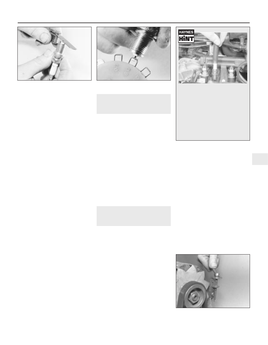
To set the gap, measure it with a feeler
blade, and then bend open, or closed, the
outer plug electrode until the correct gap is
achieved  (see illustration). The centre
electrode should never be bent, as this may
crack the insulator and cause plug failure, if
nothing worse. If using feeler blades, the gap
is correct when the appropriate-size blade is a
firm sliding fit.
10 Special spark plug electrode gap
adjusting tools are available from most motor
accessory shops, or from some spark plug
manufacturers (see illustration).
11 Before fitting the spark plugs, check that
the threaded connector sleeves are tight, and
that the plug exterior surfaces and threads are
clean (see Haynes Hint).
12 Remove the rubber hose (if used), and
tighten the plug to the specified torque using
the spark plug socket and a torque wrench.
Refit the remaining spark plugs in the same
manner.
13 Connect the HT leads in their correct
order, and refit any components removed for
access.

8

Throttle and choke cable
lubrication and adjustment

1

The throttle cable is connected to a
spring-loaded reel which pivots on the face of
the cylinder head. On certain models, the reel
then operates the throttle lever on the
carburettor through a plastic balljointed
control rod.
Sparingly apply a few drops of light oil to
the throttle spindles, linkage pivot points and
to the cable itself. Similarly lubricate the
exposed ends of the choke cable (where
fitted).
Check that there is a small amount of
slackness in the cable so that the throttle
linkage closes fully with the accelerator pedal
released. Also check that full throttle can be
obtained with the accelerator pedal fully
depressed.
If there is any doubt about the cable
adjustment, refer to the relevant Parts of
Chapter 4 for the full adjustment procedure.

9

Auxiliary drivebelt check and
renewal

2

Depending on specification, either one or
two auxiliary drivebelts are fitted. Where two
belts are fitted, it will obviously be necessary
to remove the outer belt in order to renew the
inner belt.

Checking the auxiliary drivebelt
condition

Apply the handbrake, then jack up the front
of the car and support it on axle stands.
Remove the right-hand front roadwheel.
From underneath the front of the car, prise
out the retaining clips, and remove the plastic
cover from the wing valance where necessary,
to gain access to the crankshaft
sprocket/pulley bolt.
Using a suitable socket and extension bar
fitted to the crankshaft sprocket/pulley bolt,
rotate the crankshaft so that the entire length
of the drivebelt(s) can be examined. Examine
the drivebelt(s) for cracks, splitting, fraying or

damage. Check also for signs of glazing (shiny
patches) and for separation of the belt plies.
Renew the belt if worn or damaged.
If the condition of the belt is satisfactory,
check the drivebelt tension as described below.

Auxiliary drivebelt - removal,
refitting and tensioning

Removal

If not already done, proceed as described
in paragraphs 2 and 3.
Disconnect the battery negative lead.
Slacken both the alternator upper and lower
mounting nuts/bolts (as applicable).
Push the alternator toward the engine until
the belt is slack then slip the drivebelt from
the pulleys. Where an adjuster bolt is fitted,
back off the adjuster to relieve the tension in
the drivebelt, then slip off the belt (see
illustration)
.

Refitting

10 If the belt is being renewed, ensure that
the correct type is used. Fit the belt around
the pulleys, and take up the slack in the belt

Every 12 000 miles or 12 months  

1•11

1

7.9  Measuring the spark plug gap with a

feeler blade

7.10  Measuring the spark plug gap with a

wire gauge

9.9  Slackening the alternator adjuster bolt

to release the auxiliary drivebelt

It is very often difficult to insert spark
plugs into their holes without cross-
threading them. To avoid this
possibility, fit a short length of 5/16 inch
internal diameter rubber hose over the
end of the spark plug. The flexible hose
acts as a universal joint to help align
the plug with the plug hole. Should the
plug begin to cross-thread, the hose
will slip on the spark plug, preventing
thread damage to the aluminium
cylinder head

by moving the alternator by hand, or
tightening the adjuster bolt.
11 Tension the drivebelt as described in the
following paragraphs.

Tensioning

12 If not already done, proceed as described
in paragraphs 2 and 3.
13 Correct tensioning of the drivebelt will
ensure that it has a long life. A belt which is
too slack will slip and perhaps squeal.
Beware, however, of overtightening, as this
can cause wear in the alternator bearings.
14 The belt should be tensioned so that,
under firm thumb pressure, there is
approximately 5.0 mm of free movement at
the mid-point between the pulleys on the
longest belt run.
15 To adjust, with the upper mounting
nut/bolt just holding the alternator firm, and
the lower mounting nut/bolt loosened, lever
the alternator away from the engine, or turn
the adjuster bolt until the correct tension is
achieved. Rotate the crankshaft a couple of
times, recheck the tension, then securely
tighten both the alternator mounting
nuts/bolts. Where applicable, also tighten the
bolt securing the adjuster strap to its
mounting bracket.
16 Reconnect the battery negative lead.
17 Refit the plastic cover to the wing valance.
Refit the roadwheel, and lower the vehicle to
the ground.

10 Clutch pedal stroke

adjustment

1

The clutch pedal stroke adjustment is
checked by measuring the clutch pedal travel.
Before doing this, settle the cable by
depressing and releasing it a few times.
Ensure that there are no obstructions
beneath the clutch pedal then measure the
distance from the centre of the clutch pedal
pad to the base of the steering wheel with the
pedal in the at-rest position. Depress the
clutch pedal fully to the floor, and measure the
distance from the centre of the clutch pedal
pad to the base of the steering wheel (see
illustration)
.

Subtract the first measurement from the
second to obtain the clutch pedal travel. If this
is not with the range given in the
Specifications at the start of this Chapter,
adjust the clutch as follows.
On models fitted with the BH3
transmission, loosen the locknut and turn the
adjuster on the transmission intermediate
lever pushrod as necessary. On all other
models, slacken the locknut and turn the
adjuster nut on the end of the cable.
Check the pedal stroke again and make
further adjustments as necessary. When all is
correct, tighten the relevant locknut.

11 Seat belt check

1

Check the seat belts for satisfactory

operation and condition. Inspect the webbing
for fraying and cuts. Check that they retract
smoothly and without binding into their reels.

Check the seat belt mountings, ensuring

that all the bolts are securely tightened.

12 Lock and hinge check and

lubrication

1

Check that the doors, bonnet and tailgate
close securely. Check that the bonnet safety
catch operates correctly. Check the operation
of the door check straps.
Lubricate the hinges, door check straps,
the striker plates and the bonnet catch
sparingly with a little oil or grease.
If any of the doors, bonnet or tailgate/boot
lid do not close effectively or appear not to be
flush with the surrounding panels, carry out
the relevant adjustment procedures contained
in Chapter 11.

13 Rear brake shoe check -

models with rear drum brakes

3

Remove the rear brake drums, and check the

brake shoes for signs of wear or contamination.
At the same time, also inspect the wheel
cylinders for signs of leakage, and the brake
drum for signs of wear. Refer to the relevant
Sections of Chapter 9 for further information.

14 Rear brake pad condition

check - models with rear disc
brakes

1

Chock the front wheels, then jack up the
rear of the vehicle and support it on axle
stands (see “Jacking and vehicle support”).
Remove the rear roadwheels.
For a quick check, the thickness of friction
material remaining on each brake pad can be

measured through the top of the caliper body.
If any pad’s friction material is worn to the
specified thickness or less, all four pads must
be renewed as a set.
For a comprehensive check, the brake pads
should be removed and cleaned. This will
permit the operation of the caliper to be
checked, and the condition of the brake disc
itself to be fully examined on both sides. Refer
to Chapter 9 for further information.

15 Handbrake check and

adjustment

2

Refer to Chapter 9.

16 Underbody and fuel/brake

line check

1

With the vehicle raised and supported on
axle stands (see “Jacking and vehicle
support
”), or over an inspection pit,
thoroughly inspect the underbody and wheel
arches for signs of damage and corrosion. In
particular, examine the bottom of the side
sills, and any concealed areas where mud can
collect. Where corrosion and rust is evident,
press and tap firmly on the panel with a
screwdriver, and check for any serious
corrosion which would necessitate repairs. If
the panel is not seriously corroded, clean
away the rust, and apply a new coating of
underseal. Refer to Chapter 11 for more
details of body repairs.
At the same time, inspect the treated lower
body panels for stone damage and general
condition.
Inspect all of the fuel and brake lines on the
underbody for damage, rust, corrosion and
leakage. Also make sure that they are
correctly supported in their clips. Where
applicable, check the PVC coating on the
lines for damage.
Inspect the flexible brake hoses in the
vicinity of the calipers, where they are
subjected to most movement. Bend them
between the fingers (but do not actually bend
them double, or the casing may be damaged)
and check that this does not reveal
previously-hidden cracks, cuts or splits. 

17 Exhaust system check

1

With the engine cold (at least three hours
after the vehicle has been driven), check the
complete exhaust system, from its starting
point at the engine to the end of the tailpipe.
Ideally, this should be done on a hoist, where
unrestricted access is available; if a hoist is not
available, raise and support the vehicle on axle
stands (see “Jacking and vehicle support”).

1•12

Every 12 000 miles or 12 months

10.2  To check the clutch pedal stroke,

measure the clutch pedal travel as

described in the text

Check the pipes and connections for
evidence of leaks, severe corrosion, or
damage. Make sure that all brackets and
rubber mountings are in good condition, and
tight; if any of the mountings are to be
renewed, ensure that the replacements are of
the correct type. Leakage at any of the joints
or in other parts of the system will usually
show up as a black sooty stain in the vicinity
of the leak.
At the same time, inspect the underside of
the body for holes, corrosion, open seams,
etc. which may allow exhaust gases to enter
the passenger compartment. Seal all body
openings with silicone or body putty.
Rattles and other noises can often be
traced to the exhaust system, especially the
rubber mountings. Try to move the system,
silencer(s) and catalytic converter. If any
components can touch the body or
suspension parts, secure the exhaust system
with new mountings.

18 Bodywork, paint and exterior

trim check

1

The best time to carry out this check is after
the car has been washed so that any surface
blemish or scratch will be clearly evident and
not hidden by a film of dirt.
Starting at one front corner check the
paintwork all around the car, looking for minor
scratches or more serious dents. Check all
the trim and make sure that it is securely
attached over its entire length.
Check the security of all door locks, door
mirrors, badges, bumpers, radiator grille and
wheel trim. Anything found loose, or in need
of further attention should be done with
reference to the relevant Chapters of this
manual.
Rectify any problems noticed with the
paintwork or body panels as described in
Chapter 11.

19 Headlight beam alignment

check

1

Accurate adjustment of the headlight beam

is only possible using optical beam-setting
setting equipment, and this work should
therefore be carried out by a Peugeot dealer
or service station with the necessary facilities.

Basic adjustments can be carried out in an

emergency, and further details are given in
Chapter 12.

20 Air conditioning system

check

1

Warning: The air conditioning
system is under high pressure.
Do not loosen any fittings or
remove any components until

after the system has been discharged. Air
conditioning refrigerant must be properly
discharged into an approved type of
container, at a dealer service department
or an automotive air conditioning repair
facility capable of handling the refrigerant
safely. Always wear eye protection when
disconnecting air conditioning system
fittings.
The following maintenance checks should
be performed on a regular basis, to ensure
that the system continues to operate at peak
efficiency:

a) Check the auxiliary drivebelt. If it’s worn

or deteriorated, renew it.

b) Check the system hoses. Look for cracks,

bubbles, hard spots and deterioration.
Inspect the hoses and all fittings for oil
bubbles and seepage. If there’s any
evidence of wear, damage or leaks, renew
the hose(s).

c) Inspect the condenser fins for leaves,

insects and other debris. Use a “fin

comb” or compressed air to clean the
condenser.

Warning: Wear eye protection
when using compressed air!

d) Check that the drain tube from the front

of the evaporator is clear - note that it is
normal to have clear fluid (water) dripping
from this while the system is in operation,
to the extent that quite a large puddle can
be left under the vehicle when it is parked.

It’s a good idea to operate the system for
about 30 minutes at least once a month,
particularly during the winter. Long term
non-use can cause hardening, and
subsequent failure, of the seals.
Because of the complexity of the air
conditioning system and the special
equipment necessary to service it, in-depth
repairs are not included in this manual, apart
from those procedures covered in Chapter 3.
The most common cause of poor cooling is
simply a low system refrigerant charge. If a
noticeable drop in cool air output occurs, the
following quick check will help you determine
if the refrigerant level is low.
Warm the engine up to normal operating
temperature.
Place the air conditioning temperature
selector at the coldest setting, and put the
blower at the highest setting. Open the doors
- to make sure the air conditioning system
doesn’t cycle off as soon as it cools the
passenger compartment.
With the compressor engaged - the clutch
will make an audible click, and the centre of
the clutch will rotate - feel the inlet and outlet
pipes at the compressor. One side should be
cold, and one hot. If there’s no perceptible
difference between the two pipes, there’s
something wrong with the compressor or the
system. It might be a low charge - it might be
something else. Take the vehicle to a dealer
service department or an automotive air
conditioning specialist.

21 Manual transmission oil level

check

2

Note:

The following procedure is only

applicable to models produced after
approximately October 1986. There is no
provision on the transmission for fluid level
checking on earlier transmissions (see Chapter
7A). Suitable square-section wrench may be
required to undo the transmission filler/level
plug on some models. These wrenches can be
obtained from most motor factors or your
Peugeot dealer.

Park the car on a level surface. The oil level
must be checked before the car is driven, or
at least 5 minutes after the engine has been
switched off. If the oil is checked immediately
after driving the car, some of the oil will
remain distributed around the transmission
components, resulting in an inaccurate level
reading.
Prise out the retaining clips and remove the
access cover from the left-hand wheelarch
liner.
Wipe clean the area around the filler/level
plug, which is situated on the left-hand end of
the transmission (see illustration). Unscrew
the plug and clean it; discard the sealing
washer.

Every 12 000 miles or 12 months  

1•13

1

21.3  Using a square section wrench to

unscrew the transmission filler/level plug

(MA transmission shown)

Every 24 000 miles or 2 years

The oil level should reach the lower edge of
the filler/level hole. A certain amount of oil will
have gathered behind the filler/level plug, and
will trickle out when it is removed; this does
not necessarily indicate that the level is
correct. To ensure that a true level is
established, wait until the initial trickle has
stopped, then add oil as necessary until a
trickle of new oil can be seen emerging (see
illustration)
. The level will be correct when
the flow ceases; use only good-quality oil of
the specified type (refer to “Lubricants, fluids
and capacities”
).
Filling the transmission with oil is an
extremely awkward operation; above all, allow
plenty of time for the oil level to settle properly
before checking it. If a large amount is added
to the transmission, and a large amount flows
out on checking the level, refit the filler/level
plug and take the vehicle on a short journey
so that the new oil is distributed fully around
the transmission components, then recheck
the level when it has settled again.
If the transmission has been overfilled so
that oil flows out as soon as the filler/level
plug is removed, check that the car is
completely level (front-to-rear and side-to-
side), and allow the surplus to drain off into a
suitable container.
When the level is correct, fit a new sealing
washer to the filler/level plug. Refit the plug,
tightening it to the specified torque wrench
setting. Wash off any spilt oil then refit the
access cover securing it in position with the
retaining clips.

22 Manual transmission oil

renewal

3

This service requirement is only applicable

to pre-1988 BE1 transmissions. Refer to the
procedures contained in Chapter 7A.

23 Automatic transmission fluid

renewal

2

Take the vehicle on a short run, to warm the
transmission up to normal operating
temperature.
Park the car on level ground, then switch off
the ignition and apply the handbrake firmly.
For improved access, jack up the front of the
car and support it securely on axle stands.
Note that, when refilling and checking the fluid
level, the car must be lowered to the ground,
and level, to ensure accuracy.
Remove the dipstick, then position a
suitable container under the transmission. The
transmission has two drain plugs: one on the
sump, and another on the bottom of the
differential housing (see illustration).

WarningIf the fluid is hot, take
precautions against scalding.

Unscrew both drain plugs, and allow the
fluid to drain completely into the container.
Clean the drain plugs, being especially careful
to wipe any metallic particles off the magnetic
insert. Discard the original sealing washers;

these should be renewed whenever they are
disturbed.
When the fluid has finished draining, clean
the drain plug threads and those of the
transmission casing. Fit a new sealing washer
to each drain plug, and refit the plugs to the
transmission, tightening each securely. If the
car was raised for the draining operation, now
lower it to the ground. Make sure that the car
is level (front-to-rear and side-to-side).
Refilling the transmission is an awkward
operation, adding the specified type of fluid to
the transmission a little at a time via the
dipstick tube. Use a funnel with a fine-mesh
gauze, to avoid spillage, and to ensure that no
foreign matter enters the transmission. Allow
plenty of time for the fluid level to settle
properly.
Once the level is up to the “MAX” mark on
the dipstick, refit the dipstick. Start the
engine, and allow it to idle for a few minutes.
Switch the engine off, then recheck the level,
topping-up if necessary. Take the car on a
short run to fully distribute the new fluid
around the transmission, then recheck the
fluid level as described in Section 5.

24 Driveshaft bellows check

1

With the vehicle raised and securely

supported on stands (see “Jacking and
vehicle support
”), turn the steering onto full
lock, then slowly rotate the roadwheel.
Inspect the condition of the outer constant
velocity (CV) joint rubber bellows, squeezing
the bellows to open out the folds (see
illustration)
. Check for signs of cracking,
splits or deterioration of the rubber, which
may allow the grease to escape, and lead to
water and grit entry into the joint. Also check
the security and condition of the retaining
clips. Repeat these checks on the inner CV
joints. If any damage or deterioration is found,
the bellows should be renewed as described
in Chapter 8.

At the same time, check the general

condition of the CV joints themselves by first
holding the driveshaft and attempting to
rotate the wheel. Repeat this check by holding

1•14

Every 24 000 miles or 2 years

21.4  Topping-up the transmission oil level

23.3  Automatic transmission fluid drain plugs (arrowed). Transmission is refilled via the

dipstick tube (1)

24.1  Check the condition of the driveshaft

bellows (arrowed)


содержание   ..  1  2  3  4  ..