Opel Frontera UBS. Manual - part 988
4A2A–6 DIFFERENTIAL (REAR 220mm)
11. Install the lateral rod fixing nut to the axle housing.
12. Install the stabilizer linkage mounting nut to the axle
housing.
13. Install the shock absorber fixing nut to the axle
housing.
14. Install brake tube flare nut, Refer to Disk Brakes in
Brake section.
15. Install ABS connector and bracket (ABS model only).
16. Connect breather hose.
17. Install parking brake cable, Refer to Parking Brakes in
Brake section.
18. Bleed brakes. Refer to Hydraulic Brakes in Brake
section.
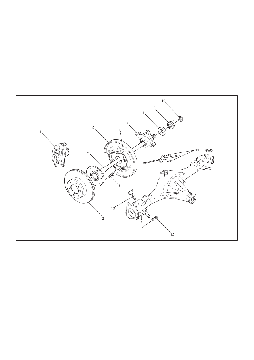
Axle Shaft
Axle Shaft and Associated Parts
420RY00005
Legend
(1) Brake Caliper
(2) Brake Disc
(3) Wheel Pin
(4) Axle Shaft Assembly
(5) Back Plate
(6) Parking Brake Assembly
(7) Bearing Holder
(8) Bearing
(9) Retainer
(10) Snap Ring
(11) Bolt
(12) Nut
(13) Antilock Brake System (ABS) Speed Sensor
Removal
1. Raise the vehicle.
2. Remove tires and wheels. Refer to Wheel in Steering
section.
3. Remove brake caliper. Use a wire to attach the brake
caliper to the frame. Refer to Disk Brakes in Brake
section.
4. Remove brake disc.
5. Remove ABS sensor.
6. Remove Parking brake assembly. Refer to Parking
Brakes in Brake section.