Index Opel Opel Frontera UBS - service repair manual 1998-2002 year
Search
Content .. 984 985 986 987 ..
Opel Frontera UBS. Manual - part 986
4A1–27
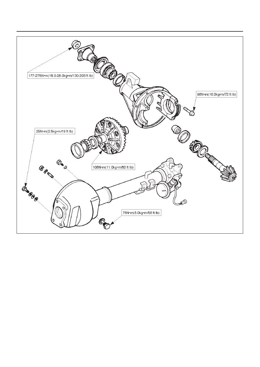
DIFFERENTIAL (FRONT)
E04RW015