Opel Frontera UBS. Manual - part 982


  Index      Opel     Opel Frontera UBS - service repair manual 1998-2002 year


Search            


Content   ..  980  981  982  983   ..


Opel Frontera UBS. Manual - part 982


4A1–11

DIFFERENTIAL (FRONT)

12. Remove dust cover.
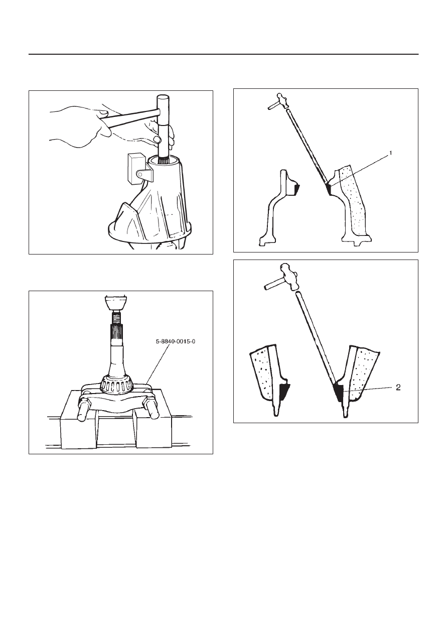
13. Remove the drive pinion assembly using a soft metal

rod and a hammer.

425RW041

14. Remove collapsible spacer.
15. Remove the inner bearing using a separator

5–8840–0015–0 and a press.

415RW033

16. Remove adjust shim.
17. Remove inner bearing outer race.
18. Remove oil seal.
19. Remove outer bearing.

20. Remove the inner bearing outer race (1) and the outer

bearing outer race (2) by using a brass bar and a
hammer.

425RS014

425RS015

DIFFERENTIAL (FRONT)

4A1–12

21. Remove damper and bracket.

425RW042

Reassembly

1. Using installer 9–8522–1141–0 and grip

5–8840–0007–0, install outer bearing outer race.

415RW018

2. Using installer 9–8522–1274–0 and grip

5–8840–0007–0, install Inner bearing outer race.

415RW017

3. Install adjust shim and adjust drive pinion mounting

distance
1. Apply gear oil to the inner and outer drive pinion

bearing.
Clean the pinion setting gauge set.
Then install the gauge set together with the inner
and outer bearings.

2. Tighten the nut to the specified torque.

Torque: 2.3 N·m (0.23kg·m/20 lb in)

415RS009

Legend

(1) Pilot : 5–8840–2085–0
(2) Nut and Bolt : 5–8840–2089–0
(3) Gauge Plate : 5–8840–2087–0

4A1–13

DIFFERENTIAL (FRONT)

3. Clean the side bearing bores. Install the dial

indicator with the discs and arbor. Install and
tighten the bearing caps to the specified torque.

Torque: 98 N·m (10kg·m/72 lb ft)

415RS010

Legend

(1) Dial Indicator: 5–8840–0126–0
(2) Disc (2 pcs.): 5-8840-2088-0
(3) Arbor: 5–8840–0128–0
(4) Gauge Plate: 5–8840–2087–0

4. Set the dial indicator to “0”. Place it on the

mounting post of the gauging arbor with the
contact button touching the indicator pad. Force
the dial indicator downward until the needle has
made a half turn clockwise. Tighten down the dial
indicator in this position.

425RS020

Legend

(1) Dial Indicator
(2) Gauging Arbor
(3) Plunger
(4) Gauge Plate

5. Position the plunger on the gauge plate. Move the

gauging arbor slowly back and forth and locate
the position at which the dial indicator shows the
greatest defection. At this point, once again set
the dial indicator to “0”.
Repeat the procedure to verify the “0” setting.

425RS021

6. After the ZERO setting is obtained, rotate the

gauging arbor until the dial indicator rod does not
touch the gauging plate.
Record the number the dial indicator needle
points to.

425RS022

Legend

(1) Example=Dial indicator reading of 0.085

DIFFERENTIAL (FRONT)

4A1–14

7. Record the pinion depth code on the head of the

drive pinion.
The number indicates a necessary change in the
pinion mounting distance. A plus number indi-
cates the need for a greater mounting distance
(which can be achieved by decreasing the shim
thickness). A minus number indicates the need
for a smaller mounting distance (which can be
achieved by increasing the shim thickness). If ex-
amination reveals pinion depth code “0”, the pin-
ion is “nominal”.

425RS023


Content   ..  980  981  982  983   ..