Opel Frontera UBS. Manual - part 971
3C – 16 FRONT SUSPENSION
INSPECTION AND REPAIR
Make necessary parts replacement if wear, damage,
corrosion or any other abnormal conditions are found
through inspection.
Check the following parts:
•
Upper control arm
•
Bushing
•
Fulcrum pin
INSTALLATION
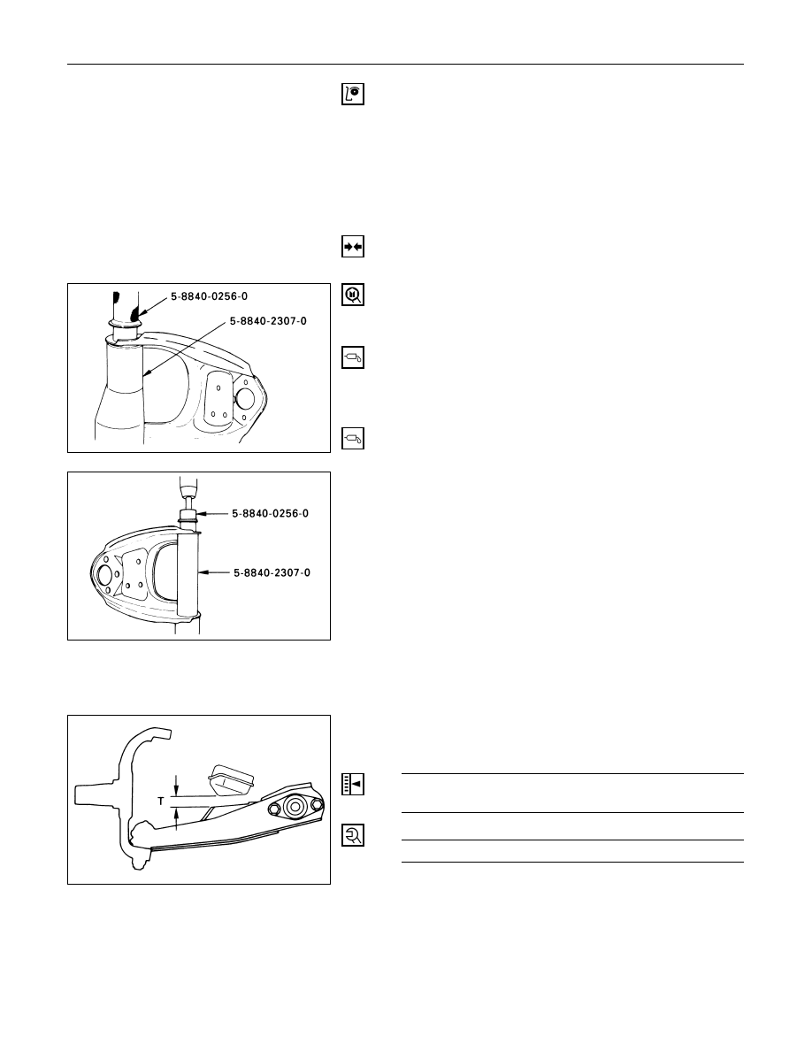
12. Fulcrum Pin
11. Bushing
Installer: 5-8840-0256-0 (J-29755) and
5-8840-2307-0 (J-39376)
10. Plate
9. Nut
Tighten fulcrum pin nut finger-tight.
NOTE:
Torque fulcrum pin nut after adjusting buffer clearance.
Buffer Clearance (T)
mm (in)
23 (0.91) Wide Tread
24 (0.94) Narrow Tread
Fulcrum Pin Nut Torque
N·m (kg·m/lb·ft)
108 (11.0 / 80)