Opel Frontera UBS. Manual - part 970
3C – 12 FRONT SUSPENSION
10. Knuckle
INSPECTION AND REPAIR
Make necessary correction or parts replacement if wear,
damage, corrosion or any other abnormal condition are
found through inspection.
Check the following parts:
•
Knuckle
•
Needle bearing
•
Thrust washer
INSTALLATION
10. Knuckle
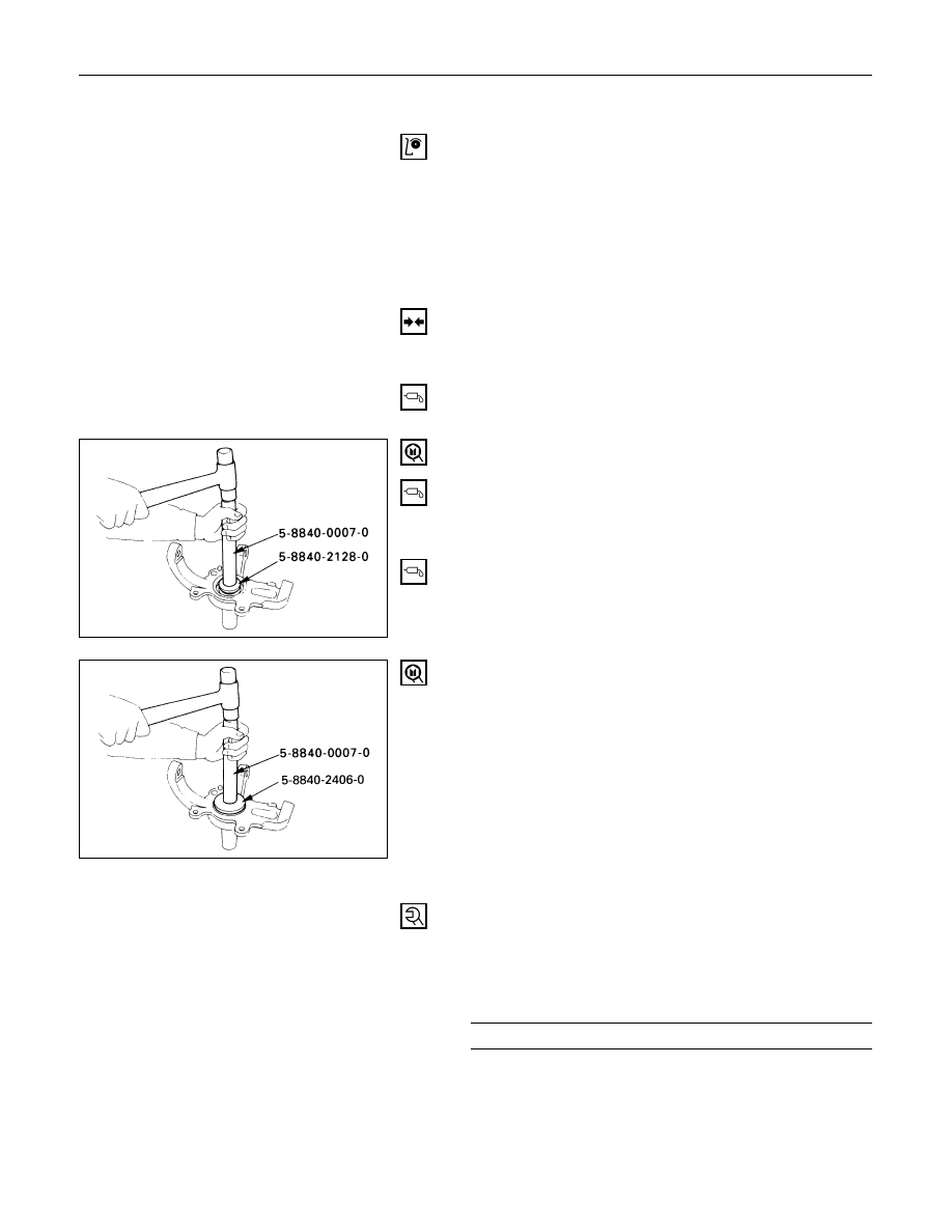
9. Needle Bearing
Before installation, apply appropriate amount of
multipurpose type grease to the new bearing (Approx.
5 g).
Installer: 5-8840-2128-0 (J-36838) and
5-8840-0007-0 (J-8092)
8. Washer
Apply multipurpose type grease to the thrust washer,
and install it with chamfered side facing knuckle.
7. Oil Seal
Use a new oil seal, and apply multipurpose type
grease to the area surrounded by the lip (approx. 2 g).
After fitting the oil seal to the installer, drive it to the
knuckle using a hammer or bench press until the tool
front face contacts with the thrust washer.
Installer: 5-8840-2406-0 (J-41468)and
5-8840-0007-0 (J-8092)
6. Knuckle Assembly
5. Upper Ball Joint
Tighten the nut to the specified torque, with just
enough additional torque to align cotter pin holes.
Install new cotter pin.
Upper Ball Joint Nut Torque
N·m (kg·m/lb·ft)
98 (10.0 / 72)