Opel Frontera UBS. Manual - part 934


  Index      Opel     Opel Frontera UBS - service repair manual 1998-2002 year


Search            


Content   ..  932  933  934  935   ..


Opel Frontera UBS. Manual - part 934


1B–130 AIR CONDITIONING
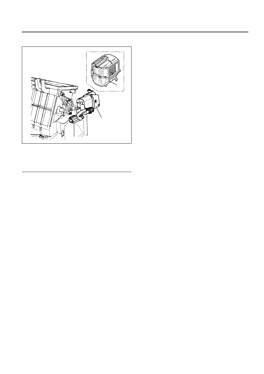
Intake Actuator

Legend

(1)

Evaporator Assembly

(2)

Intake Actuator

(3)

Intake Actuator Connector

Removal

1. Disconnect the battery ground cable.

2. Discharge and recover refrigerant.

Refer to Refrigerant Recovery in this section.

3. Remove the evaporator assembly.

Refer to Eevaporator Assembly section.

4. Disconnect the intake actuator connector.

5. Remove the intake actuator.

Installation

To install, follow the removal step in the reverse
order.

1

2

3

860RX018

This illustration is based on RHD

COMPRESSOR OVERHAUL  1D – 1

CAUTION

When fasteners are removed, always
reinstall them at the same location from
which they were removed. If a fastener
needs to be replaced, use the correct part
number fastener for that application. If the
correct part number fastener is not available,
a fastener of equal size and strength (or
stronger) may be used. 

Fasteners that are not reused, and those
requiring thread locking compound, will be
called out. The correct torque values must
be used when installing fasteners that
require it. If the above conditions are not
followed, parts or system damage could
result.

SECTION 1D

COMPRESSOR OVERHAUL

CONTENTS

PAGE

General Description . . . . . . . . . . . . . . . . . . . . . . . . . . . . . . . . . . . . . . . . . . . . . . . . . . . . . 1D– 2

General Information . . . . . . . . . . . . . . . . . . . . . . . . . . . . . . . . . . . . . . . . . . . . . . . . . . . . . 1D– 4

Compressor Oil . . . . . . . . . . . . . . . . . . . . . . . . . . . . . . . . . . . . . . . . . . . . . . . . . . . . . . . 1D– 4

Service Procedures . . . . . . . . . . . . . . . . . . . . . . . . . . . . . . . . . . . . . . . . . . . . . . . . . . . . . . 1D– 6

DKV-14D Type Compressor . . . . . . . . . . . . . . . . . . . . . . . . . . . . . . . . . . . . . . . . . . . . . 1D– 6

DKS-15CH Type Compressor . . . . . . . . . . . . . . . . . . . . . . . . . . . . . . . . . . . . . . . . . . . . 1D–10

HD6 Type Compressor . . . . . . . . . . . . . . . . . . . . . . . . . . . . . . . . . . . . . . . . . . . . . . . . . 1D–18

SECTION

1D – 2 COMPRESSOR OVERHAUL

GENERAL DESCRIPTION

When servicing the compressor, keep dirt or foreign
material from getting on or into the compressor
parts and system. Clean tools and a clean work area
are important for proper service. The compressor
connections and the outside of the compressor

should be cleaned before any “On-Vehicle” repair,
or before removal of the compressor. The parts
must be kept clean at all times and any parts to be
reassembled should be cleaned with
Trichloroethane, naphtha, kerosene, or equivalent

DKS-15CH TYPE

DKV-14D TYPE

871RY00014

COMPRESSOR OVERHAUL  1D – 3

solvent, and dried with dry air. Use only lint free
cloths to wipe parts.
The operations described below are based on
bench overhaul with compressor removed from the
car, except as noted. They have been prepared in
order of accessibility of the components. When the
compressor is removed from the car for servicing,
the oil remaining in the compressor should be
discarded and new refrigerant oil added to the
compressor.
Magnetic clutch assembly repair procedures require
that the system be discharged of refrigerant. (Refer
to Section 1B for “REFRIGERANT RECOVERY”.)
Compressor malfunction will appear in one of four
ways: noise, seizure, leakage or low discharge
pressure. Resonant compressor noises are not
cause for alarm; however, irregular noise or rattles
may indicate broken parts or excessive clearances
due to wear. To check seizure, de-energize the
magnetic clutch and check to see if the drive plate
can be rotated. If rotation is impossible, the
compressor is seized. Low discharge pressure may
be due to a faulty internal seal of the compressor,
or a restriction in the compressor. Low discharge
pressure may also be due to an insufficient
refrigerant charge or a restriction elsewhere in the
system. These possibilities should be checked prior
to servicing the compressor. If the compressor is
inoperative, but is not seized, check to see if current
is being supplied to the magnetic clutch coil
terminals.
The compressor has vanes built into a rotor which
is mounted on a shaft.
When the shaft rotates, the vanes built into the
cylinder block assembly are opened by centrifugal
force.
This changes the volume of the space formed by
the rotor and cylinder, resulting in the intake and
compression of the refrigerant gas. The discharge
valve and the valve stopper, which protects the
discharge valve, are built into the cylinder block
assembly. There is no suction valve but a shaft seal
is installed between the shaft and head; a trigger
valve, which applies back pressure to the vanes, is
installed in the cylinder block and a refrigerant gas
temperature sensor is installed in the front head.
The specified quantity of compressor oil is
contained in the compressor to lubricate the various
parts using the refrigerant gas discharge pressure.

6VD1 engine is equipped with an invariable
capacity five-vane rotary compressor (DKV-14D
Type).
The compressor sucks and compresses refrigerant
by the rotation of the vane installed to the shaft,
and always discharges a fixed amount of refrigerant
independent of the load of refrigerant.

The thermo sensor is installed to the front head of
the compressor to protect it by stopping its
operation when the refrigerant gas is insufficient or
when the temperature get abnormally high.

OFF ..... 160 

±

5°C (320.0 

±

9.0°F)

ON ..... 135 

±

5°C (275.0 

±

9.0°F) 

4JG2 Engine are provided with a swash plate type
compressor (DKS-15CH Type)
Swash plate compressors have a swash (slanted)
plate mounted on the shaft. When the shaft turns,
the rotation of the swash plate is converted to
reciprocating piston motion which sucks in and
compresses the refrigerant gas.
Shaft seal (Lip type) is installed between the valve
plate and shaft & cylinder head to prevent
refrigerant gas leaks. A specified amount of
compressor oil is contained in the oil pan.
This oil is supplied to the cylinders, bearings, etc.,
by an oil pump which is connected to the swash
plate shaft.
With some compressors the differential between
the intake pressure and discharge pressure
generated while the compressor is operating is
used for lubrication instead of an oil pump.
Three pistons are arranged at 120g intervals around
the center of the swash plate shaft. These pistons
are connected to the ends of the swash plate
through shoe disks and balls.
The rotation of the swash plate causes
reciprocating movement of the piston inside the
cylinders, with each piston operating as two
cylinders. Because of that, the compressor operates
as though it has 6 cylinders.
The specified amount of the compressors oil is
150cc (4.2 Imp fl oz).
Also, compressor oil to be used varies according to
the compressor model. Be sure to avoid mixing two
or more different types of oil.
If the wrong oil is used, lubrication will be poor and
the compressor will seize or malfunction.


Content   ..  932  933  934  935   ..