Opel Frontera UBS. Manual - part 903
1B – 6 AIR CONDITIONING
DUAL PRESSURE SWITCH
The dual pressure switch is installed on the upper
part of the receiver/drier, to detect excessively high
pressure (high pressure switch) and prevent
compressor seizure due to the refrigerant leaking
(low pressure switch), switching the compressor
“ON” or “OFF” as required.
The pressure switch connector is waterproof type.
•
Low-pressure control
kpa (kg·cm
2
/ PSI)
Compressor
ON: 205.9 ± 30 (2.1 ± 0.3 / 30 ± 4)
(Except 6VD1 / 6VE1, LHD model)
186 ± 30 (1.9 ± 0.3 / 27 ± 4)
(only for 6VD1 / 6VE1, LHD model)
OFF: 176 ± 20 (1.8 ± 0.2 / 26 ± 3)
•
High-pressure control
Compressor
ON: 2354 ± 196 (24.0 ± 2.0 / 341 ± 28)
OFF: 2942 ± 196 (30.0 ± 2.0 / 427 ± 28)
TRIPLE PRESSURE SWITCH
Triple pressure switch is installed atop the receiver/
drier. This switch is constructed with a unitized type
of two switches. One of them is a low and high
pressure switch (Dual pressure switch) to switch
“ON” or “OFF” the magnetic clutch as a result of
irregularly high-pressure or low-pressure of the
refrigerant. The other one is a medium pressure
switch (Cycling switch) to switch “ON” or “OFF”
the condenser fan sensing the condenser high side
pressure.
•
Low-pressure control
kpa (kg·cm
2
/PSI)
Compressor
ON: 186 ± 30 (1.9 ± 0.3 / 27 ± 4)
OFF: 176 ± 20 (1.8 ± 0.2 / 26 ± 3)
•
Medium-pressure control
Condenser fan
ON: 1471 ± 98 (15.0 ± 1.0 / 213 ± 14)
OFF: 1079 ± 98 (11.0 ± 1.0 / 156 ± 14)
•
High-pressure control
Compressor
ON: 2354 ± 196 (24.0 ± 2.0 / 341 ± 28)
OFF: 2942 ± 196 (30.0 ± 2.0 / 427 ± 28)
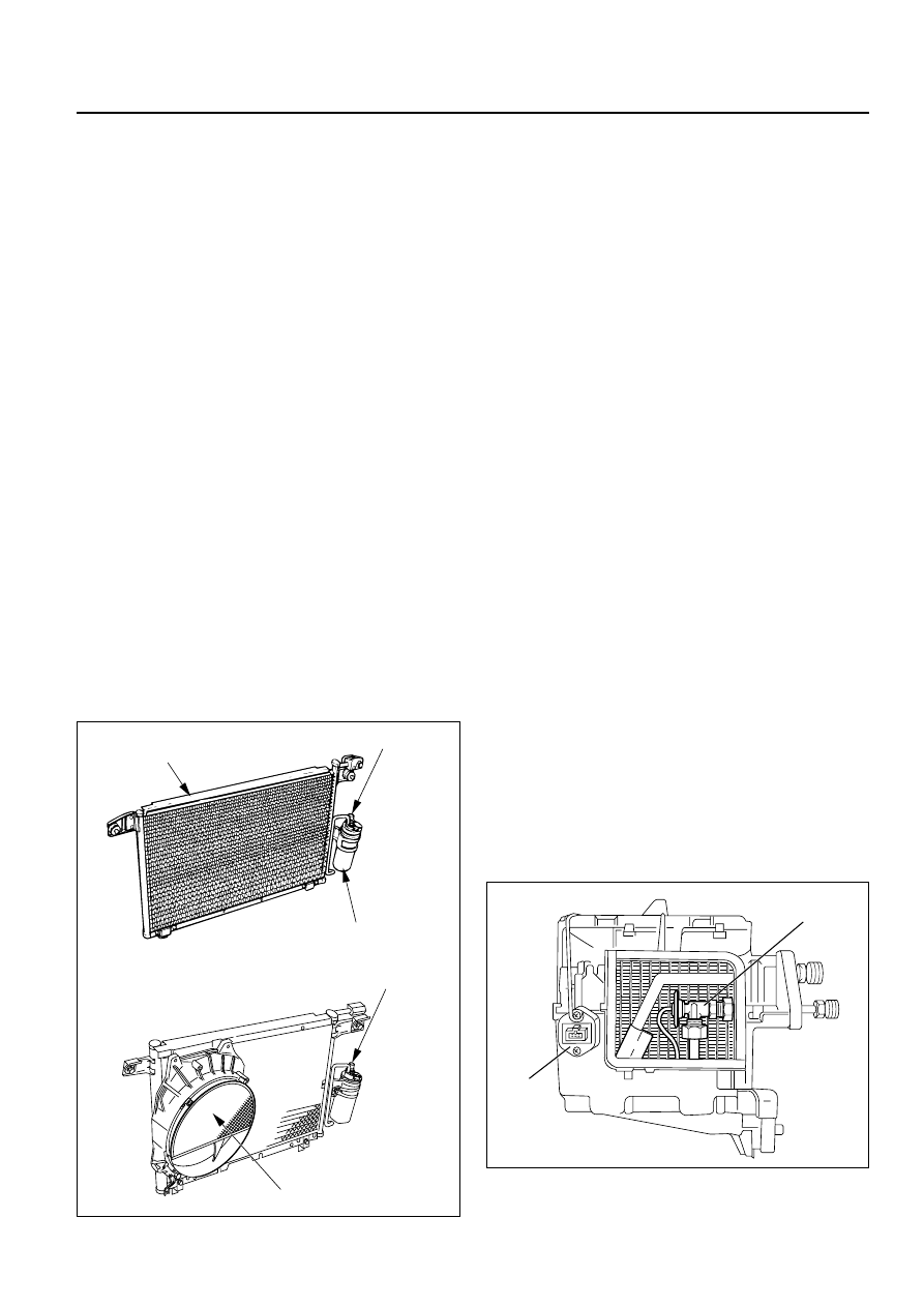
EXPANSION VALVE
This expansion valve (1) is internal pressure type
and it is installed at the evaporator intake port.
The expansion valve converts the high pressure
liquid refrigerant sent from the receiver/drier to a
low pressure liquid refrigerant by forcing it through
a tiny port before sending it to the evaporator (2).
This type of expansion valve consists of a
temperature sensor, diaphragm, ball valve, ball
seat, spring adjustment screw, etc.
The temperature sensor contacts the evaporator
outlet pipe, and converts changes in temperature to
pressure. It then transmits these to the top chamber
of the diaphragm.
The refrigerant pressure is transmitted to the
diaphragms bottom chamber through the external
equalizing pressure tube.
The ball valve is connected to the diaphragm. The
opening angle of the expansion valve is determined
by the force acting on the diaphragm and the spring
pressure.
The expansion valve regulates the flow rate of the
refrigerant. Accordingly, when a malfunction occurs
to this expansion valve, both discharge and suction
pressures get low, resulting in insufficient cooling
capacity of the evaporator.
Pressure switch
Receiver/Drier
Triple pressure switch
Condenser fan
Condenser
1
2
875RY00003
874RY00003