Opel Frontera UBS. Manual - part 644


  Index      Opel     Opel Frontera UBS - service repair manual 1998-2002 year


Search            


Content   ..  642  643  644  645   ..


Opel Frontera UBS. Manual - part 644


8D–6

WIRING SYSTEM

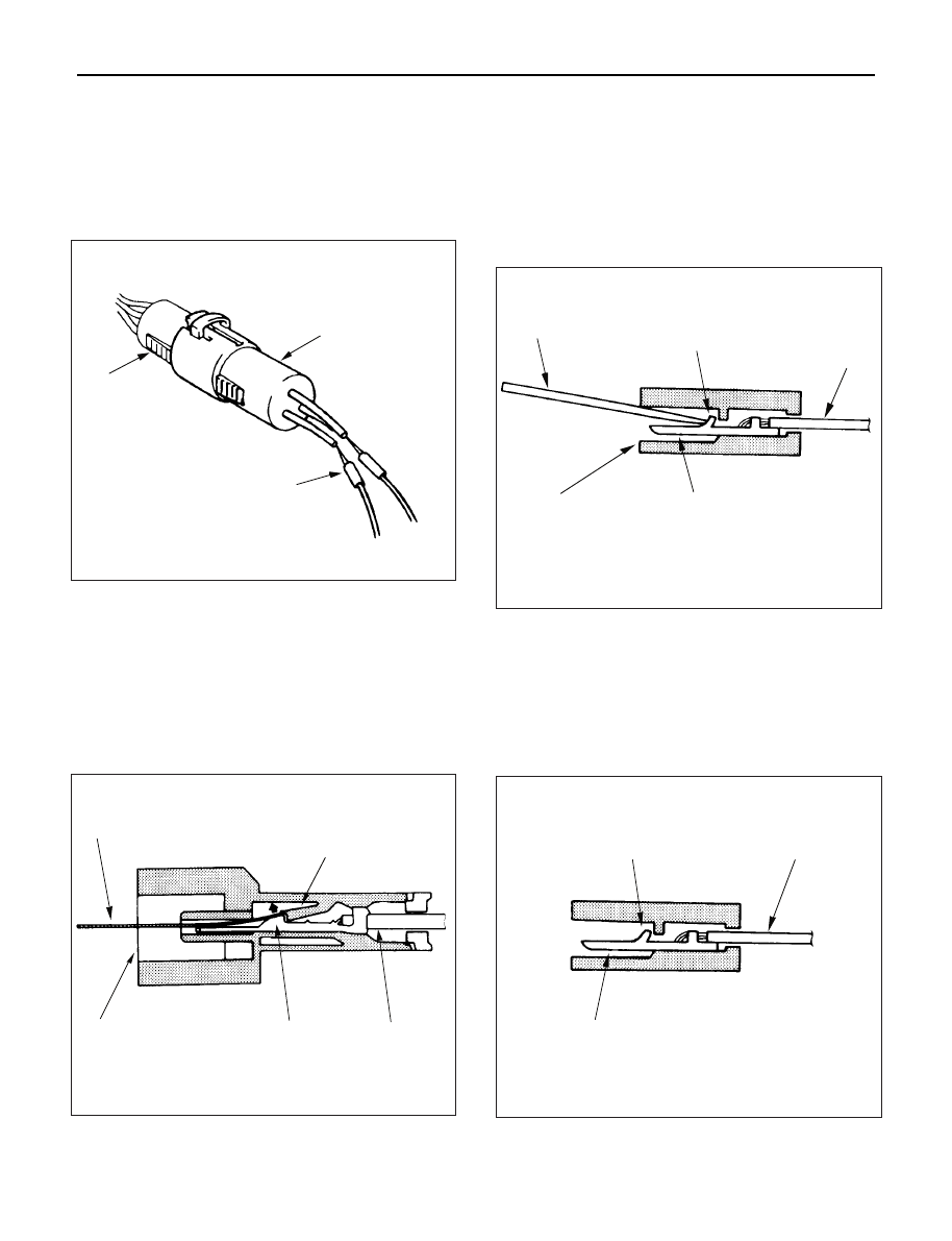
Waterproof Connector Inspection

It is not possible to insert the test probes (2) into the
connector wire side of a waterproof connector.
Use one side of a connector (1) with its wires cut to make
the test. Connect the test connector to the connector to
be tested (3). Connect the test probes to the cut wires to
check the connector continuity.

Connector Pin Removal – Connector
Housing Tang Lock Type

1. Insert a slender shaft (1) into the connector housing

open end (5).

2. Push the tang lock (2) up (in the direction of the arrow

in the illustration).
Pull the wire (3) with pin (4) free from the wire side of
the connector.

Connector Pin Removal – Pin Tang Lock
Type

1. Insert a slender shaft (1) into the connector housing

open end (5).

2. Push the tang lock (2) flat (toward the wire (3) side of

the connector.
Pull the wire with pin (4) free from the wire side of the
connector.

Connector Pin Insertion

1. Check that the tang lock (1) is fully up.
2. Insert the pin (3) from the connector wire (2) side.

Push the pin in until the tang lock closes firmly.

3. Gently pull on the wires to make sure that the

connector pin is firmly set in place.

1

3

2

1

2

3

5

4

1

2

3

4

5

1

2

3

WIRING SYSTEM

8D–7

Parts Handling

Be careful when handling electrical parts. They should not
be dropped or thrown, because short circuit or other
damage may result.

Cable Harness

1. When installing the parts, be careful not to pinch or

wedge the wiring harness.

2. All electrical connections must be kept clean and tight.

3. Use a grommet or guard tube (1) to protect the wiring

harness from contacting a sharp edge or surface (2).

4. Position the wiring harness with enough clearance

from the other parts and guard the wiring harness with
a vinyl tube (2) and clips (1) to avoid direct contact.

1

2

2

1

8D–8

WIRING SYSTEM

5. The wiring harness between engine and chassis

should be long enough (2). Tension of the wire (1) may
causes chafing or damage due to various vibrations.

Splicing Wire

1. If the harness is taped, remove the tape. To avoid wire

insulation damage, use a sewing “seam ripper”
(available from sewing supply stores) to cut open the
harness.
If the harness has a black plastic conduit, simply pull
out the desired wire.

2. Begin by cutting as little wire off the harness as

possible. You may need the extra length of wire later
if you decide to cut more wire off to change the location
of a splice. You may have to adjust splice locations to
make certain that each splice is at least 1–1/2”
(40 mm) away from other splices, harness branches,
or connectors.

3. When replacing a wire, use a wire of the same size as

the original wire.
Check the stripped wire for nicks or cut stands. If the
wire is damaged, repeat the procedure on a new
section of wire. The two stripped wire ends should be
equal in length.

4. Select the proper clip to secure the splice.

To determine the proper clip size for the wire being
spliced, follow the directions included with your clips.
Select the correct anvil on the crimper. (On most
crimpers your choice is limited to either a small or
large anvil.)
Overlap the two stripped wire ends and hold them
between your thumb and forefinger as shown in the
figure.
The center the spline clip (1) under the stripped wires
and hold it in place.

Open the crimping tool to its full width and rest one
handle on a firm flat surface.

Center the back of the splice clip on the proper anvil
and close the crimping tool to the point where the back
of the splice clip touches the wings of the clip.

Make sure that the clip and wires are still in the correct
position. Then, apply steady pressure until the
crimping tool closes as shown in the figure.

2

1

1

WIRING SYSTEM

8D–9

Before crimping the ends of the clip (1), be sure that:

The wires extend beyond the clip in each direction.

No strands of wire are cut loose, and

No insulation is caught under the clip.

Crimp the splice again, once on each end.
Does not let the crimping tool (2) extend beyond the edge
of the clip or you may damage or nick the wires as shown
in the figure.

5. Apply 60/40 resin core solder to the opening in the

back of the clip as shown in the figure.
Follow the manufacturer’s instructions for the solder
equipment you are using.

6. Center and roll the splicing tape.

The tape should cover the entire splice.
Roll on enough tape (1) to duplicate the thickness of
the insulation on the existing wires.
Does not flag the tape (2). Flagged tape may not
provide enough insulation, and the flagged ends will
tangle with the other wires in the harness as shown in
the figure.

If the wire does not belong in a conduit or other
harness covering, tape the wire again. use a winding
motion to cover the first piece of tape as shown in the
figure.

1

2

1

2


Content   ..  642  643  644  645   ..