Opel Frontera UBS. Manual - part 626
7C–18
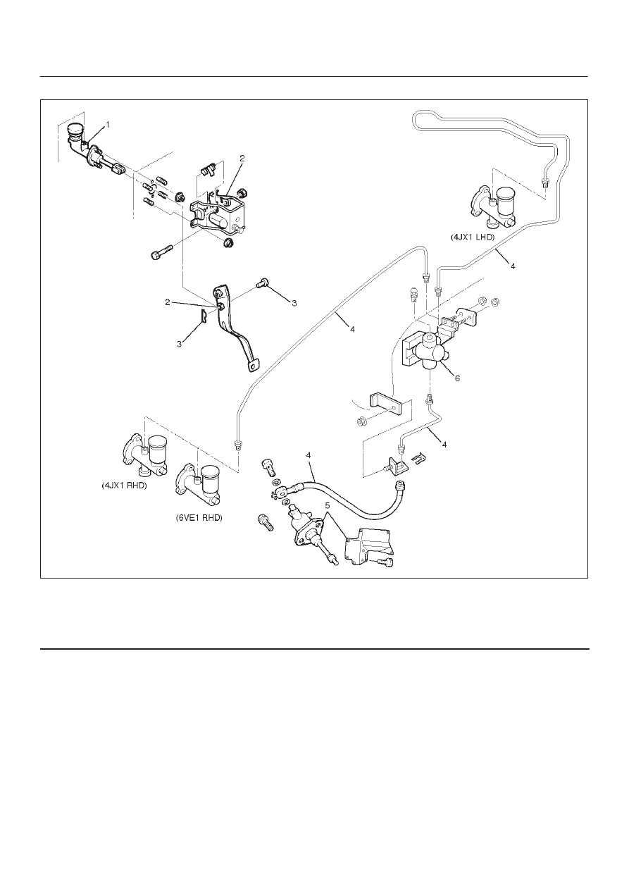
CLUTCH
(Except 6VE1 LHD)
203RW009
Legend
(1) Master Cylinder Assembly
(2) Pedal Assembly
(3) Pin and Joint Pin
(4) Oil Line Pipe
(5) Slave Cylinder Assembly and Heat Protector
(6) Damper Cylinder Assembly
Removal
1. Remove pin and jaw joint pin.
2. Remove pedal assembly.
3. Remove oil line pipe.
4. Remove slave cylinder assembly and heat protector.
5. Remove master cylinder assembly.
6. Remove damper cylinder assembly (except V6 LHD).
Inspection and Repair
Make necessary adjustments, repairs, and part
replacement if wear, damage or other problems are
discovered during inspection.