Opel Frontera UBS. Manual - part 551


  Index      Opel     Opel Frontera UBS - service repair manual 1998-2002 year


Search            


Content   ..  549  550  551  552   ..


Opel Frontera UBS. Manual - part 551


7A–73

AUTOMATIC TRANSMISSION (4L30–E)

247RW006

2. Remove spring seat (2) and springs (3). 
3. Remove piston assembly (4). 
4. Remove 8 bolts from center support (5), then remove

center support (5) from adapter case. 

5. Remove gasket transfer plate/outer support (6),

center support transfer plate (7), and gasket transfer
plate/adapter case (8).

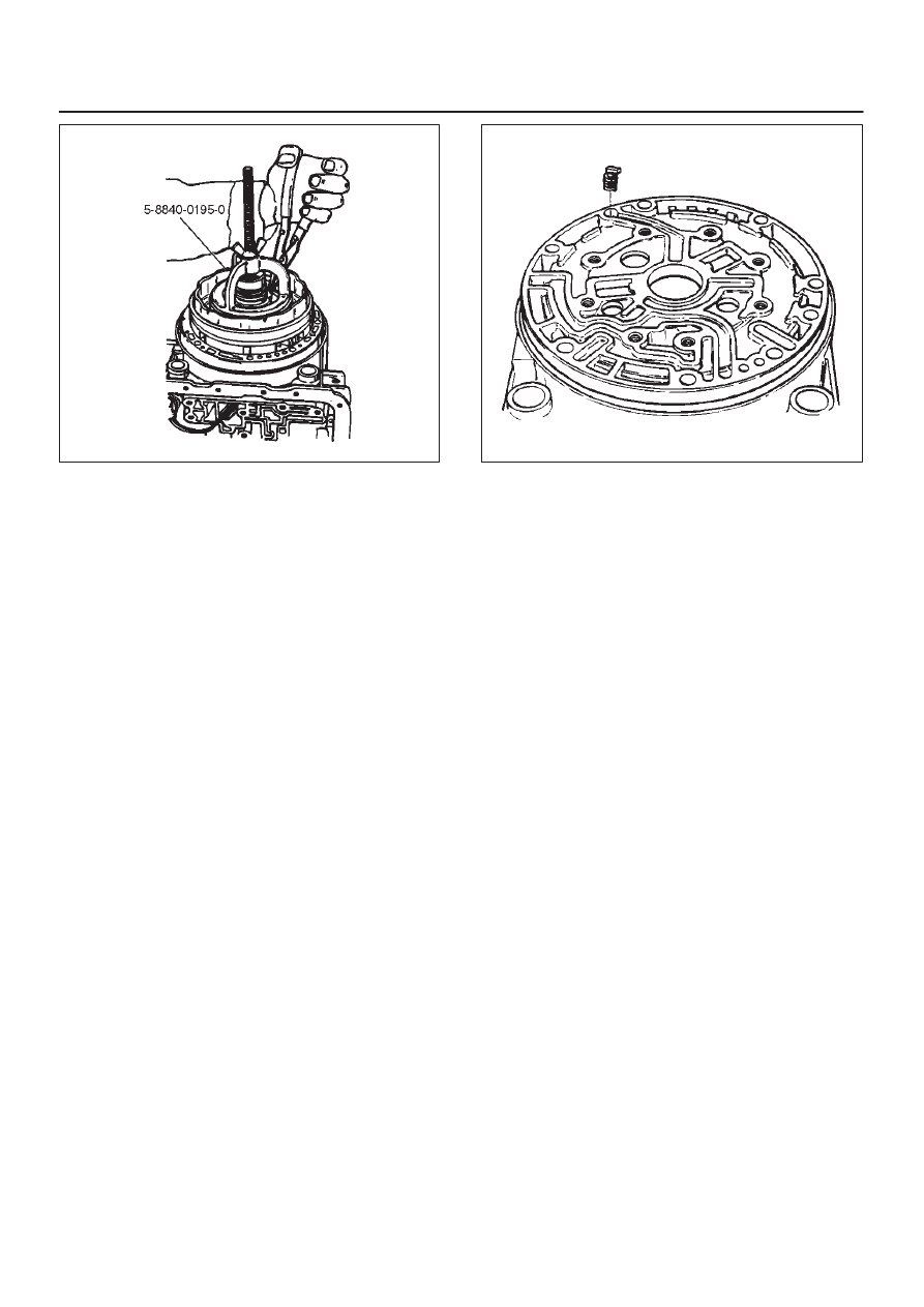
6. Remove restrictor (9) from adapter case housing. 
7. Remove retainer plate (10), plug (11), spring (12), and

overrun lock out valve (13) from center support (5). 

Inspection And Repair

Visual Check:

If any damage, deformation or wear is found, replace the
damaged part.

Reassembly

1. Install overrun lock out valve (13) and spring (12) to

center support.

NOTE: Ensure correct assembly of valve. The spring
should be located over the long small diameter end.

2. Install plug (11) and retainer plate (10). 
3. Place restrictor (9) in the lube overdrive channel in the

adapter case housing.

242RS005

4. Install gasket transfer plate/adapter case (8), center

support transfer plate (7), and gasket transfer
plate/center support (6). 

5. Install center support (5) with 8 bolts.

Torque : 25 N

m (2.5 kg·m/18 lb ft)

6. Install piston assembly (4) into center support (5). 
7. Install twenty four springs (3), spring seat (2), and

retaining ring (1).

D

Install the 5–8840–0195–0 (J–23327) compressor
and compress spring seat (2) and springs (3), then
seat snap ring (1) in groove.

D

Remove the tool.

7A–74

AUTOMATIC TRANSMISSION (4L30–E)

Overrun Clutch And Turbine Shaft

Disassembled View

252RW005

Legend

(1) Snap Ring
(2) Overdrive Carrier Assembly
(3) Sun Gear
(4) Turbine Shaft
(5) Snap Ring
(6) Backing Plate
(7) Clutch Plates

(8) Snap Ring
(9) Overrun Roller Clutch Cam

(10) Roller Clutch Assembly

(11) Overrun Clutch Release Spring Retainer

(12) Diaphragm Spring
(13) Piston Assembly
(14) Overrun Clutch Drum
(15) Turbine Shaft Seal Rings

Disassembly

1. Position overrun clutch assembly upright, using the

overdrive internal gear as a support.

D

Remove snap ring (1).

7A–75

AUTOMATIC TRANSMISSION (4L30–E)

252RS009

2. Remove overdrive carrier assembly (2), sun gear (3)

and turbine shaft (4). 

3. Remove snap ring (5), backing plate (6), and clutch

plates (7). 

4. Compress diaphragm spring with the

5–8840–2275–0 (J–23327–91) compressor, then
remove snap ring (8).

252RW011

5. Remove overrun roller clutch cam (9) and roller clutch

assembly (10). 

6. Remove overrun clutch release spring retainer (11)

and diaphragm spring (12). 

7. Remove piston assembly (13) from overrun clutch

drum (14). 

8. Remove turbine shaft seal rings (15).

Inspection And Repair

Overdrive Carrier Check

D

Check pinion end play with a feeler gauge.

Clearance: 0.24mm–0.64mm (0.0094in–0.025in)

If clearance is outside specified value, replace overdrive
carrier assembly.

252RS011

Visual Check:

If any damage, deformation or local wear is found,
replace the damaged part.

Reassembly

1. Install turbine shaft seal rings (15) with grease

(petroleum jelly).

241RS008

7A–76

AUTOMATIC TRANSMISSION (4L30–E)

2. Install the 5–8840–2269–0 (J–38555) inner installer

on the drum (14).

D

Pre–install piston assembly into 5–8840–2269–0
(J–38555) outer installer.

D

Install overrun clutch piston assembly (13).  Use the
outer installer while pushing piston into drum (14).

D

Remove the installer.

252RW012

252RW013

3. Install diaphragm spring (12).
4. Install overrun clutch release spring retainer (11) (lip

faces upwards), overrun roller clutch assembly (10),
and cam (9).

5. Place snap ring loosely on spring retainer.

D

Hold the 5–8840–2275–0 (J–23327–91)
compressor in a vise and compress piston return
spring with compressor.

D

Set snap ring (8) in ring groove.

D

Remove the compressor.

6. Install clutch plates (7), start with steel plate and

alternate with lined plates.

7. Install backing plate (6). 

8. Install snap ring (5). 
9. Install overdrive sun gear with countersink pointing

downwards.

10. Install the overdrive carrier assembly (2).

NOTE: Turn the assembly in a counter–clockwise
direction only until roller clutch enters the outer race.
After installation, rotate the assembly and listen for loose
rollers. 

11. Install turbine shaft (4) and snap ring (1).


Content   ..  549  550  551  552   ..