Opel Frontera UBS. Manual - part 523
6E–222
4JX1–TC ENGINE DRIVEABILITY AND EMISSIONS
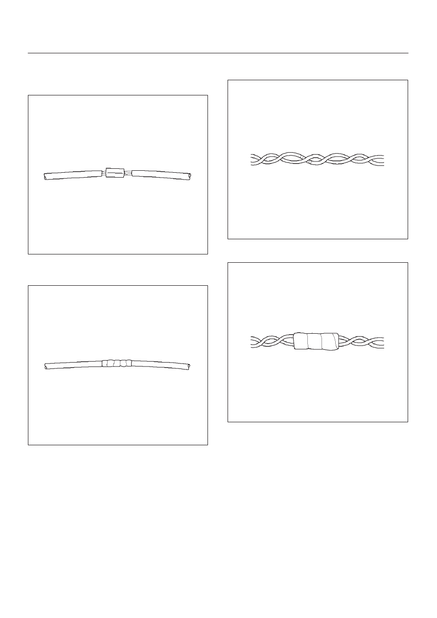
Installation Procedure
1. Use splice clips and rosin core solder in order to splice
the two wires together.
052
2. Cover the splice with tape in order to insulate it from
the other wires.
053
3. Twist the wires as they were before starting this
procedure.
054
4. Tape the wires with electrical tape. Hold in place.
055