Opel Frontera UBS. Manual - part 489


  Index      Opel     Opel Frontera UBS - service repair manual 1998-2002 year


Search            


Content   ..  487  488  489  490   ..


Opel Frontera UBS. Manual - part 489


6E–86

4JX1–TC ENGINE DRIVEABILITY AND EMISSIONS

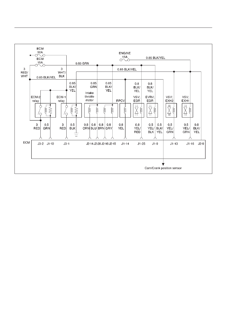
Diagnostic Trouble Code (DTC) P1193 (Flash DTC 64) 

RPCV Circuit Open/Short

060RW135

Circuit Description

The rail pressure control valve (RPCV) is built in the high
pressure oil circuit.
RPCV is an important device which is used to control oil
pressure in the HEUI system.
The circuit receives current through Engine 15A fuse from
the battery, current flowing in the order of RPCV.

Action Taken When the DTC Sets

D

The ECM will store conditions which were present
when the DTC was set as Freeze Frame and in the
Failure Records data.

Conditions for Clearing the MIL/DTC

D

DTC P1193 can be cleared by using the Tech 2 “Clear
Info” function or by disconnecting the ECM battery
feed.

Diagnostic Aids

Check for the following conditions:

D

Poor connection at ECM – Inspect harness connectors
for backed-out terminals, improper mating, broken
locks, improperly formed or damaged terminals, and
poor terminal-to-wire connection.

D

Damaged harness – Inspect the wiring harness for
damage.  If the harness appears to be OK, observe the
RPCV display on the Tech 2 while moving connectors
and wiring harnesses related to the RPCV.  A change
in the RPCV display will indicate the location of the
fault.

If DTC P1193 cannot be duplicated, the information
included in the Failure Records data can be useful in
determining vehicle mileage since the DTC was last set.
If it is determined that the DTC occurs intermittently.

6E–87

4JX1–TC ENGINE DRIVEABILITY AND EMISSIONS

DTC P1193 – RPCV  Circuit Open/Short


Step

Action

Value(s)

Yes

No

1

Was the “On-Board Diagnostic (OBD) System Check”
performed?

Go to 

Step 2

Go to 

OBD

System

Check

2

1. Ignition “ON,” engine “ON.”
2. Observe the “Rail Oil Pressure” display on the Tech

2.

Is the “Rail Oil Pressure” below the specified value?

3.5 

 5 Mpa

Go to 

Step 4

Go to 

Step 3

3

Replace the RPCV.

Is the action complete?

Go to 

Step 2

4

1. Engine “On”.
2. Using the Tech 2, operate “RPCV”.
3. Check the combustion noise.

Was the combustion noise change?

Go to 

Step 5

5

Check the RPCV circuit. (Fuse 15A to J1-14)

Was the RPCV circuit damaged?

Go to 

Step 6

Go to 

Step 7

6

Repair the RPCV circuit.

Is the action complete?

Verify repair

7

Replace the ECM (Refer to the Data Programming in
Case of ECM change).

Is the action complete?

Verify repair

Go to 

Step 8

8

Replace the high pressure oil pump.

Is the action complete?

Verify repair

6E–88

4JX1–TC ENGINE DRIVEABILITY AND EMISSIONS

Diagnostic Trouble Code (DTC) P1194 (Flash DTC 61) 

Rail Pressure System Low Voltage

060RW134

Circuit Description

The rail pressure (RP) sensor responds to changes in oil
rail pressure.
The ECM monitors the RP signals for voltages outside the
normal range of the RP sensor.  If the ECM detects a RP
signal voltage that is excessively low, DTC P1194 will be
set.

Action Taken When the DTC Sets

D

The ECM will store conditions which were present
when the DTC was set as Freeze Frame and in the
Failure Records data.

Conditions for Clearing the MIL/DTC

D

DTC P1194 can be cleared by using the Tech 2 “Clear
Info” function or by disconnecting the ECM battery
feed.

Diagnostic Aids

Check for the following conditions:

D

Check for intermittent codes.

D

Poor connection at ECM – Inspect harness connectors
for backed-out terminals, improper mating, broken
locks, improperly formed or damaged terminals, and
poor terminal-to-wire connection.

D

Damaged harness – Inspect the wiring harness for
damage.  If the harness appears to be OK, observe the
MAP display on the Tech 2 while moving connectors
and wiring harnesses related to the sensor.  A change
in the display will indicate the location of the fault.

If DTC P1194 cannot be duplicated, the information
included in the Failure Records data can be useful in
determining vehicle mileage since the DTC was last set.
If it is determined that the DTC occurs intermittently,
performing the DTC P1194 Diagnostic Chart may isolate
the cause of the fault.

6E–89

4JX1–TC ENGINE DRIVEABILITY AND EMISSIONS

DTC P1194 – RP System Low Voltage


Step

Action

Value(s)

Yes

No

1

Was the “On-Board Diagnostic (OBD) System Check”
performed?

Go to 

Step 2

Go to 

OBD

System

Check

2

1. Engine is running.
2. Review and record Tech 2 Failure Records data.
3. Operate the vehicle within Failure Records

conditions as noted.

4. Using a Tech 2, monitor “DTC” info for DTC P1194.

Does the Tech 2 indicate DTC P1194 failed?

Go to 

Step 3

Refer to

Diagnostic

Aids

3

Connect a test light between B+ and the RP sensor
signal circuit at the RP sensor  harness connector.

Is the RP value near the specified value.

5 V

Go to 

Step 4

Go to 

Step 6

4

1. Ignition “OFF.”
2. Disconnect the ECM and check the 5 volt reference

“J2” circuit for an open or short to ground.

3. If the 5 volt reference “J2” circuit is open or shorted

to ground, repair it as necessary.

Was the 5 volt reference “J2” circuit open or shorted to
ground?

Verify repair

Go to 

Step 5

5

Check the 5 volt reference “J2” circuit for a poor
connection at the ECM and replace the terminal if
necessary.

Did the terminal require replacement?

Verify repair

Go to 

Step 6

6

1. Ignition “OFF.”
2. Disconnect the ECM, and check the RP signal

circuit for an open, short to ground, or short to the
sensor ground circuit.

3. If the RP sensor signal circuit is open or shorted to

ground, repair it as necessary.

Was the RP signal circuit open or shorted to ground?

Verify repair

Go to 

Step 7

7

Check the RP sensor signal circuit for a poor
connection at the ECM and the RP sensor; replace the
terminal if necessary.

Did the terminal require replacement?

Verify repair

Go to 

Step 8

8

Replace the ECM (Refer to the Data Programming in
Case of ECM change).

Is the action complete?

Verify repair

Go to 

Step 9

9

Check the 2 way valve.

Was the 2 way valve darmage?

Replace the 2

way valve

Go to 

Step 10

10

Replace the RPCV.

Is the action complete?

Verify repair

Go to 

Step 11

11

Replace the RP sensor.

Is the action complete?

Verify repair


Content   ..  487  488  489  490   ..