Opel Frontera UBS. Manual - part 389


  Index      Opel     Opel Frontera UBS - service repair manual 1998-2002 year


Search            


Content   ..  387  388  389  390   ..


Opel Frontera UBS. Manual - part 389


ENGINE MECHANICAL 6A – 29

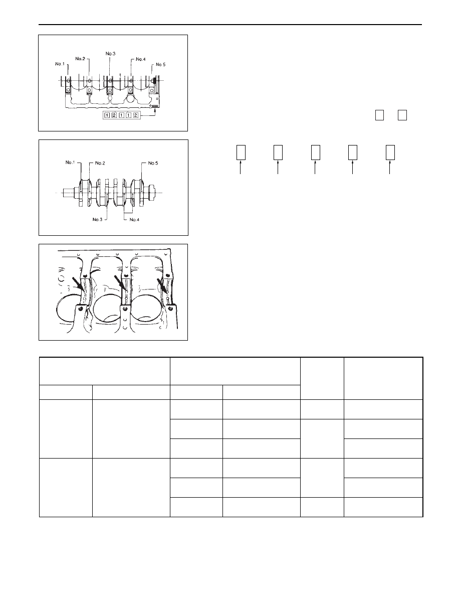
Crankshaft Bearing Selection

When installing new crankshaft bearings or replacing old
bearings, refer to the selection table below.
Select and install the new crankshaft bearings, paying close
attention to the cylinder body journal hole 1 diameter size
mark and the crankshaft journal 2 diameter size mark.

Crankshaft Bearing Housing Grade Mark Position

Crankshaft bearing housing grade marks  1  or  2  are
stamped on the rear right hand side of the cylinder body.

Example:

Crankshaft Journal Grade Mark Position

The crankshaft journal grade marks (1 or –) are stamped on
each crankshaft journal web.
The crankshaft journal and bearing clearance must be the
same for each position after installation of the crankshaft
and the crankshaft bearings.
Note:

The crankshaft journal mark No. 4 is stamped on crankshaft
No. 4 journal web front side or rear side.

NOTE:

Although all upper journal bearings (cylinder body side)
have oil grooves and holes, all lower bearings (bearing
cap side) have no groove and hole.
Play close attention to the distinction during the installa-
tion procedure.

Main Bearing

Bore Diameter mm(in.)

Crankshaft

Main Journal Diameter mm(in.)

Size Mark

Inside Diameter

Grade Mark

Outside Diameter

Crankshaft

Bearing

Grade Mark

Oil Clearance

mm (in.)

1 or   - 

69.927 ~ 69.932

(2.7530 ~ 2.7532)

2 or  - -

69.922 ~ 69.927

(2.7528 ~ 2.7530)

3 or - - -

69.917 ~ 69.922

(2.7526 ~ 2.7528)

1 or   -

69.927 ~ 69.932

(2.7530 ~ 2.7532)

2 or  - - 

69.922 ~ 69.927

(2.7528 ~ 2.7530)

3 or - - -

69.917 ~ 69.922

(2.7526 ~ 2.7528)

Black

Blue

Green

Black

73.987 ~ 74.000

(2.9129 ~ 2.9134)

73.975 ~ 73.987

(2.9124 ~ 2.9129)

1

2

0.035 ~ 0.061

(0.0014 ~ 0.0024)

0.032 ~ 0.058

(0.0013 ~ 0.0023)

0.037 ~ 0.063

(0.0015 ~ 0.0025)

0.031 ~ 0.056

(0.0012 ~ 0.0022)

0.036 ~ 0.048

(0.0014 ~ 0.0019)

0.033 ~ 0.058

(0.0013 ~ 0.0023)

No. 1 Bearing

Housing

No. 2 Bearing

Housing

No. 3 Bearing

Housing

No. 4 Bearing

Housing

No. 5 Bearing

Housing

1

2

1

1

2

6A – 30 ENGINE MECHANICAL

REASSEMBLY

14. Crankshaft

Install the main bearings to the cylinder body and
the main bearing caps.

Be sure that they are positioned correctly.

Apply new engine oil to the upper and lower main
bearing faces.

Carefully mount the crankshaft.

Apply engine oil to the thrust washer.

Assemble the thrust washer to the No. 3 bearing
journal.  The oil grooves must face the crankshaft.

13. Main Bearing Cap

Apply the recommended liquid gasket or its equiva-
lent to the No. 5 crankshaft bearing cap 1 as shown
in the illustration.

Install the arch gasket 2 

to the No. 5 bearing cap.

Use your fingers to push the arch gasket into the
bearing cap groove.

NOTE

Take care not to scratch the arch gasket outer surface.

Apply the recommended liquid gasket or its equiva-
lent to the No. 5 crankshaft bearing cap cylinder
body fitting surfaces at points 3 and 4 shown in the
illustration.

NOTE:

Be sure that the bearing cap fitting surface is completely
free of oil before applying the liquid gasket.
Do not allow the liquid gasket to obstruct the cylinder
thread holes and bearings.

ENGINE MECHANICAL 6A – 31

Install the bearing caps with the bearing cap head
arrow mark facing the front of the engine.

Apply engine oil to the crankshaft bearing cap bolts.

Tighten the crankshaft bearing cap bolts to the
specified torque a little at a time in the sequence
shown in the illustration.

NOTE:

Check to see that the crankshaft turns smoothly by rotating
it manually.

12. Piston and Connecting Rod Assembly

Apply engine oil to the cylinder bores, the connect-
ing rod bearings and the crankshaft pins and each
piston ring and piston.
Check to see that the piston ring end gaps are
correctly positioned.

29 (3.0/22)

N·m(kg·m/lb.ft)

Oiling Jet Plug

10. Oil Pump Assembly

1) Prepare a solution of 80% engine oil and 20%

molybdenum disulfide.

2) Apply an ample coat of the solution to the teeth of

the oil pump pinion.

3) Install the oil pump and tighten the bolts to the

specified torque.

After tightening the cap nuts, check to see that the
crankshaft rotates smoothly.

11. Piston Cooling Oil Pipe

Tighten the bolt and oiling jet plug to the specified
torque

Insert the piston/connecting rod assemblies into
each cylinder with the piston ring compressor.
Piston ring compressor: 5-8840-9018-0
The front marks must be facing the front of the
engine.

Match the numbered caps with the numbers on the
connecting rods.  Align the punched marks on the
connecting rods and caps.

Apply engine oil to the threads and seating faces of
the nuts.

Tighten the cap nuts in 2 steps, using angular tight-
ening method as shown in the following specifica-
tions.

167 (17.0/123)

N·m(kg·m/lb·ft)

N·m (kg·m/lb·ft)

45

°

 ~ 60

°

1st step

2nd step

29 (3.0/22)

N·m (kg·m/lb·ft)

19 (1.9/14)

M6

8 (0.8/6)

M8

6A – 32 ENGINE MECHANICAL

19 (1.9/14)

N·m(kg·m/lb·ft)

5.

Timing Gear Case

1)

Install the timing gear case to the cylinder body.

NOTE:

Take care not to twist the front oil seal.

6.

Flywheel

1) Thoroughly clean and remove the oil from the

threads of crankshaft.

2) Mount the flywheel on the crankshaft and then

install the washer.

3) Align the flywheel with the crankshaft dowel pin.
4) Tighten the flywheel bolts to the specified torque

in the numerical order shown in the illustration.

82 (8.4/61)

N·m(kg·m/lb·ft)

NOTE:

Take care not to damage the O-rings when tightening the
oil pipe bolts.

9.

Crankcase Assembly

Refer to “Crankcase” Section 6A2

8.

Crankshaft Rear Oil Seal

1) Tighten the adapter to the crankshaft rear and

section with 2 bolts.

2) Insert the oil seal into the peripheral section of the

adapter,

3) Insert the sleeve into the adapter section, and 1)

tighten it with a bolt (M12 x 1.75L = 70) until the
adapter section hits the sleeve.

4) Remove the adapter and the sleeve.
5) With the seal pressed in, check the dimension of

the oil seal section.

Standard Dimension = 12.5 ± 0.3 mm

Oil Seal Installer:

5-8840-2359-0

7.

Cylinder Block Rear Plate

Align the rear plate with the cylinder body knock pins.
Tighten the rear plate to the specified torque.

118 (12.0/87)

N·m(kg·m/lb·ft)


Content   ..  387  388  389  390   ..