Opel Frontera UBS. Manual - part 287
6E–54
ENGINE DRIVEABILITY AND EMISSIONS
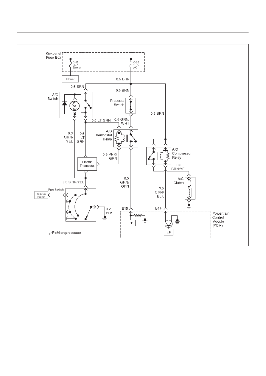
A/C Clutch Control Circuit Diagnosis
D06RW085
Circuit Description
When air conditioning and blower fan are selected, and if
the system has a sufficient refrigerant charge, a 12-volt
signal is supplied to the A/C request input of the
powertrain control module (PCM). The A/C request
signal may be temporarily canceled during system
operation by the electronic thermostat in the evaporator
case. The electronic thermostat may intermittently
remove the control circuit ground for the A/C thermostat
relay to prevent the evaporator from forming ice. When
the A/C request signal is received by the PCM, the PCM
supplies a ground from the compressor clutch relay if the
engine operating conditions are within acceptable
ranges. With the A/C compressor relay energized,
voltage is supplied to the compressor clutch coil.
The PCM will enable the compressor clutch to engage
whenever A/C has been selected with the engine running,
unless any of the following conditions are present:
D
The throttle is greater than 90%.
D
The ignition voltage is below 10.5 volts.
D
The engine speed is greater than 4500 RPM for 5
seconds or 5400 RPM.
D
The engine coolant temperature (ECT) is greater than
125
°
C (257
°
F).
D
The intake air temperature (IAT) is less than 5
°
C
(41
°
F).
D
The power steering pressure switch signals a cramped
position.
Diagnostic Aids
To diagnose an the intermittent fault, check for the
following conditions:
D
Poor connection at the PCM–Inspect connections for
backed-out terminals, improper mating, broken locks,
improperly formed or damaged terminals, and poor
terminal-to-wire connection.