Opel Frontera UBS. Manual - part 2703


  Index      Opel     Opel Frontera UBS - service repair manual 1998-2002 year


Search            


Content   ..  2701  2702  2703  2704   ..


Opel Frontera UBS. Manual - part 2703


8D–12

WIRING SYSTEM

Parts for Electrical Circuit

Wiring – Wire color

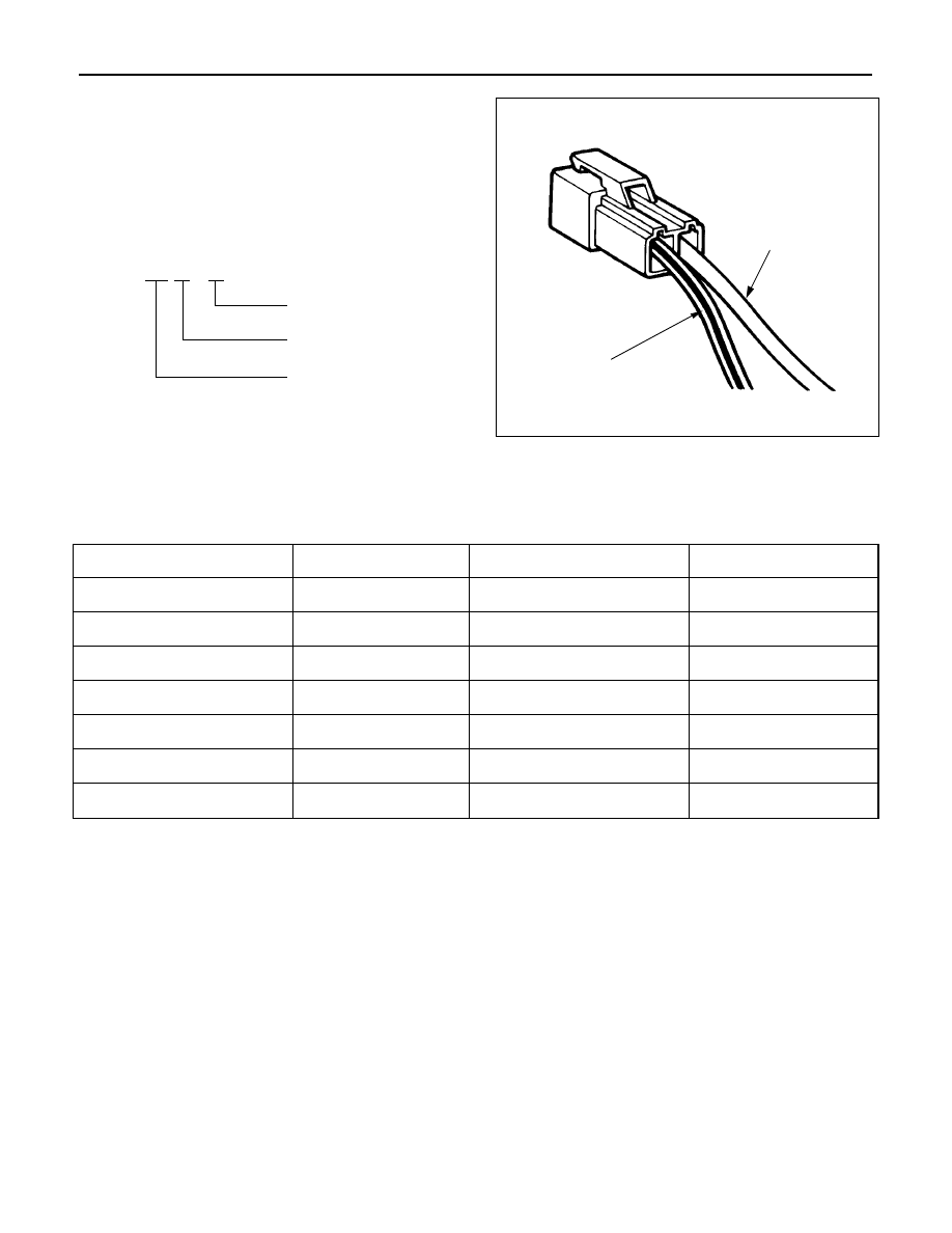
All wires have color–coded insulation.
Wires belonging to a system’s main harness will have a
single color (1). Wires belonging to a system’s subcircuits
will have a colored stripe (2). Striped wires use the
following code to show wire size and colors.

Example: 0.5 G / R

Red (Stripe color)

Green (Base color)

Wire size (0.5 mm

2

)

Wiring – Wire Color Coding

Abbreviations are used to indicate wire color within a circuit diagram.
Refer to the following table.

Color Coding

Meaning

Color Coding

Meaning

B

Black

BR

Brown

W

White

LG

Light green

R

Red

GR

Grey

G

Green

P

Pink

Y

Yellow

LB

Light blue

L

Blue

V

Violet

O

Orange

1

2

WIRING SYSTEM

8D–13

Wiring – Wire Size

The size of wire used in a circuit is determined by the
amount of current (amperage), the length of the circuit,
and the voltage drop allowed. The following wire size and
load capacity are specified.  (Nominal size means
approximate cross sectional area (1).)

Wiring – Wire Size Table

Nominal size

Cross sectional

Outside diameter

Allowable

area (mm

2

)

(mm)

current (A)

0.3

0.372

1.5

9

0.5

0.563

1.7

12

0.85

0.885

1.9

16

1.25

1.287

2.2

21

2

2.091

2.7

28

3

3.296

3.6

37.5

5

5.227

4.4

53

8

7.952

5.5

67

15

13.36

7.0

75

20

20.61

8.2

97

1

8D–14

WIRING SYSTEM

Fuse

Fuses are the most common form of circuit protection
used in vehicle wiring. A fuse is a thin piece of wire or strip
of metal encased in a glass or plastic housing. It is wired
in series with the circuit it protects. When there is an
overload of current in a circuit, such as a short of a ground,
the metal strip is designed to burn out and interrupt the
flow of current. This prevents a surge of high current from
reaching and damaging other components in the circuit.
Determine the cause of the overloaded before replacing
the fuse.
The replacement fuse must have the same amperage
specification as the original fuse.
Never replace a blown fuse with a fuse of a different
amperage specification.
Doing so can result in an electrical fire or other serious
circuit damage. A blown fuse is easily identified as shown
in the figure.

WIRING SYSTEM

8D–15

Fusible Link

The fusible link is primarily used to protect circuits where
high amounts of current flow and where it would not be
practical to use a fuse. For example, the starter circuit.
When a current overload occurs, the fusible link melts
open and interrupts the flow of current so as to prevent
the rest of the wiring harness from burning.
Determine the cause of the overload before replacing the
fusible link. the replacement fusible link must have the
same amperage specification as the original fusible link.
Never replace a blown fusible link with fusible link of a
different amperage specification. Doing so can result in
an electrical fire or other serious circuit damage.
A blown fusible link is easily identified as shown in the
figure.

Normal

Blown

Fusible Link Specifications

Type

Rating

Case Color

Maximum Circuit Current (A)

Connector

30A

Pink

15

Connector

40A

Green

20

Bolted

50A

Red

25

Bolted

60A

Yellow

30

Bolted

80A

Black

40


Content   ..  2701  2702  2703  2704   ..