Opel Frontera UBS. Manual - part 257
6A–95
ENGINE MECHANICAL
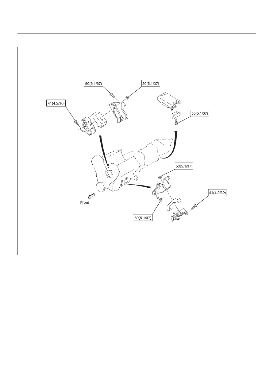
Engine mount
N·m (Kg·m/Ib ft)
E06RW040